7 Circuit Diagrams Thermo 90
706
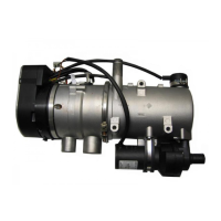
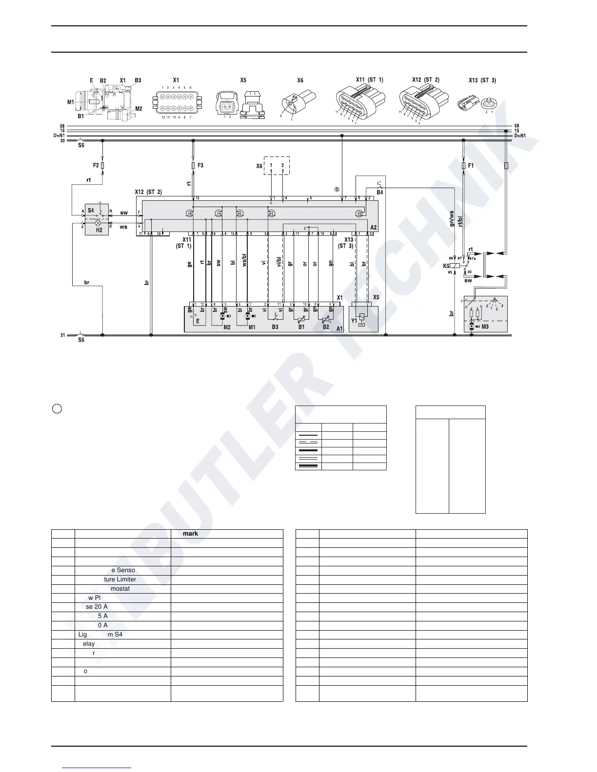
Fig. 706 Circuit Diagram Automatic Control for Thermo 90 S-TRS, 24 V without Auxiliary Drive
ϑϑ
Temperature coding (temperature at water outlet):
see table page 302
2
bl
br
ge
gn
gr
or
rt
sw
vi
ws
Wire colors
blue
brown
yellow
green
gray
orange
red
black
violet
white
Wire gauges
< 7.5 m 7.5 - 15 m
0.75 mm
2
1.0 mm
2
1.5 mm
2
2.5 mm
2
4.0 mm
2
1.5 mm
2
1.5 mm
2
2.5 mm
2
4.0 mm
2
6.0 mm
2
Item Nomenclature Remark
A1 Heater Thermo 90 / Thermo 90 S
A2 Control Unit
B1 Flame Sensor
B2 Temperature Sensor
B3 Temperature Limiter
B4 Room Thermostat
E Glow Plug
F1 Fuse 20 A Flat Fuse SAE J 1284
F2 Fuse 5 A Flat Fuse SAE J 1284
F3 Fuse 20 A Flat Fuse SAE J 1284
H2 Light in item S4 Operation indication (max. 2 W)
K5 Relay for vehicle blower
M1 Motor Combustion air fan
M2 Motor Circulation pump
M3 Motor Vehicle blower
S4 Switch ON / OFF
S5 Isolation Switch 1-pole or 2-pole Emergency off switch electr. or
pne
um.
Item Nomenclature Remark
X1 Connection 12-pole on item A1
X5 Connection 12
-pole
X6 Connection 12
-pole Diagnosis
X11 Connection 12-pole on item A2 (ST 1)
X12 Connection 12-pole on item A2 (ST 2)
X13 Connection 12
-pole on item A2 (ST 3)
Y1 Dosing Pump

 Loading...