Notice: Never operate the pump with the discharge valve completely closed. The pump can destroy itself if run at
shutoff pressure.
Notice: Never start a pump with the discharge valve completely open, if the pump will operate at high flow - low head
or if the pump is placed in an artesian well. This can cause the pump to up thrust the impellers-shaft
assembly, which can cause premature wear and failure.
To test the well water for clarity, attach a temporary horizontal length of pipe
and gate valve to the riser pipe.
Make sure the controls are in the off position. Connect the motor leads and
power supply to control box, electrical disconnect box or magnetic starter. See
wiring diagrams. Do not start the pump!
Partially open the gate valve and start pump. To make sure the 3 phase motor
is running in the right direction, note the direction of jerk as the motor starts.
If connections are properly made, the pump will jerk clockwise when looking
into the pump discharge when started. If the jerk is counter - clockwise, the
motor is running in the wrong direction. Interchange any two cable leads where
they connect to the lead terminals in the magnetic starter. Restart the pump
and let it operate until the water runs clear of sand, silt and other impurities.
When the water is completely clear at the initial gate valve setting, slowly open
valve in small increments allowing the water to clear before progressing. The
pump should not be stopped until the water runs clear.
Remove the gate valve for permanent installation.
Install a sanitary well seal or pitless adapter, submersible pump/motor, electrical conduit and surface piping according to
local code requirements.
Control Box
or Electrical
Disconnect Box
Temporary Wiring
Temporary Piping
Gate Valve
Pump Installation
for Developing a Well
Pump in Well
Figure 1
Make sure that the pump has been properly grounded prior to testing.
Starting Procedure
- 4 -
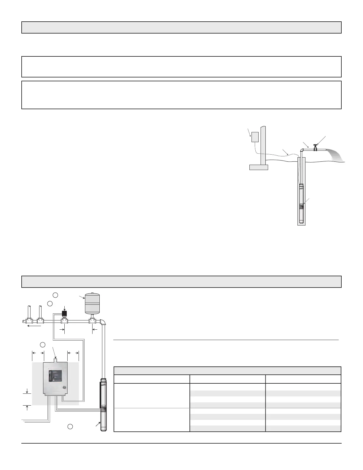
Pump & Motor
Controller
Clearance
For Airflow
6"
min.
Constant Water
Pressure To House
6 Feet or less
(Pressure tank to
Pressure Sensor)
Pressure Tank
6"
min.
6"
min.
Pressure Sensor
1
2
4
3
Webtrol has added the SubDrive Systems using 3PH motors, and Utility Drive
Systems designed for use with 3 wire motors. Both Systems will deliver water at a
constant pressure. Carefully read and follow all the safety instructions in the
“Installation Manual” that is shipped with the SubDrive/Utility Drive Series Systems.
SubDrive/Utility Drive Systems
Webtrol’s SubDrive/Utility Drive System consists of only 4 components:
1) Webtrol’s standard pump & motor assembly. 3) Pressure tank
2) SubDrive/MonoDrive controller. 4) Pressure sensor.
Pump Flow Rating Controller Model Minimum Tank Size
SubDrive 75 or Utility Drive 2 gallons
Less than 12 GPM SubDrive 100 4 gallons
SubDrive 150 or Utility Drive 4 gallons
SubDrive 300 8 gallons
SubDrive 75 or Utility Drive 4 gallons
12 GPM or higher SubDrive 100 8 gallons
SubDrive 150 or Utility Drive 8 gallons
SubDrive 300 20 gallons
Minimum Pressure Tank Size (Total Capacity)
Figure 2
 Loading...