- 5 -
The submersible motor requires a minimum flow of
water past the motor to insure proper cooling. Table 1
below shows the minimum flow rates in GPM for vari-
ous diameters and motor size.
If the flow rate is less than specified, a flow inducer
sleeve or an alternate method of increasing water
velocity past the motor must be used for proper cooling.
Several conditions requiring a flow sleeve are; the
pump is in an open body of water, the well is top feed-
ing and the well diameter is too large to meet Table 1
flow requirements.
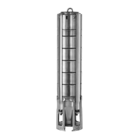
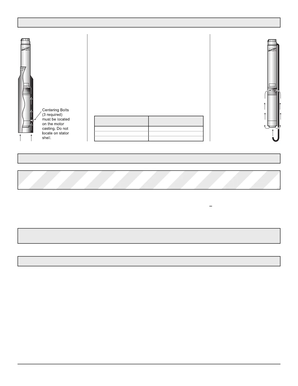
Flow Inducer
Sleeve
Flow Inducer
Discharge Tube
A flow inducer sleeve is
a tube over the motor,
closed off above the
pump intake and
extended to the bottom
of the motor or lower.
The sleeve material is
corrosion resistant
metal or heavy plastic.
If the casing is too small
for a flow inducer sleeve
and the pump cannot be
raised, a tube may be
installed as follows:
A. Tap a 1/4” tube (ID)
into the pump outlet
(below check valve).
B. Clamp it to the pump
and motor.
C. Aim tube upward so
flow is introduced 1
foot below the motor.
D. Protect tube with
spacers and angle iron.
Inches Casing 4” Dia. Motor
or Sleeve I.D. .25 ft/sec GPM
4 1.2
5 7
6 13
Electrical supply must match the motor voltage, phase and frequency found on the nameplate on the motor and control box.
Motor electrical data can be found in tables 4, 4A, 5 & 5A. If voltage variations are larger than + 10%, do not operate the pump.
On 3 phase installations, use a magnetic starter and quick trip overload heaters. Failure to use quick trip heaters in all three lines
will not provide adequate motor protection and the warranty will be void.
Warning: A faulty motor or wiring can be an electrical shock hazard if it or surrounding water is accessible to human
contact. To prevent this from occurring, connect the motor frame to the power supply grounding terminal with
a stranded copper conductor no smaller than the wires carrying current to the motor.
Caution: Use of smaller than recommended cable voids warranty, can cause failure of the motor to start and operate
properly and may cause cable overheating!
Table 1
Submersible Motor Cooling
Electrical
Sizes given are for copper wire. If aluminum wire is used, it must be two sizes larger and oxidation inhibitors must be used on
the connections. Example: If the table calls for #12 copper wire, #10 aluminum wire would be required.
Note: #11 wire is available, but not often used.
Maximum lengths shown maintain motor voltage at 95% of service entrance voltage, running at maximum nameplate amperes.
To comply to CSA, multiply the cable lengths shown by .6 for maximum feet. This will maintain motor voltage at 97% of service
entrance voltage, running at maximum nameplate amperes.
The portion of the total cable length which is between the supply and single phase control box with a line contactor, should not
exceed 25% of total maximum allowable to ensure reliable contactor operation. Single phase control boxes without line contac-
tors may be connected at any point in the total cable length.
Cable Information
 Loading...