
J
Jared GilbertAug 15, 2025
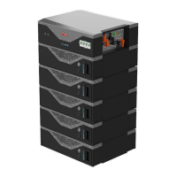
How to fix over current alarm on Weco HeSU 4k4 PRO Battery Pack?
- LLisa HoganAug 15, 2025
If you are experiencing an over current alarm with your Weco Battery Pack, it means the battery relay is disconnected during charging or discharging, and the battery fault light is flashing. To resolve this, reduce the charge or discharge current.