5
ASSEMBLY
WARNING: Stop the unit and dis-
connect f rom the power source before
opening the inlet cover or att empti ng to in-
sert or remove the inlet restrictor , blower
tube, or vacuum tubes. The motor must
be stopped and the im pell er blades no
lo nger turning to avoi d serious inju ry from
the r ot ati ng bl ades.
WARNING: I f recei ved assembl ed ,
ensur e your unit is properly assem bled
and all f astener s ar e secure.
S A standard screwdriver is required for as-
sembly.
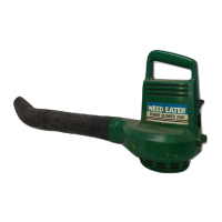
BLOWER ASSEMBLY
NOTE: Assembly inst r u ct ions for usi ng
your unit as a vacuum foll ow t hi s section.
Attaching the blower tube
If you have already assembled your unit
for use as a vacuum, refer to the section
HOW TO CONVERT UNIT FROM VACUUM
USE TO BLOWER USE.
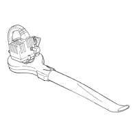
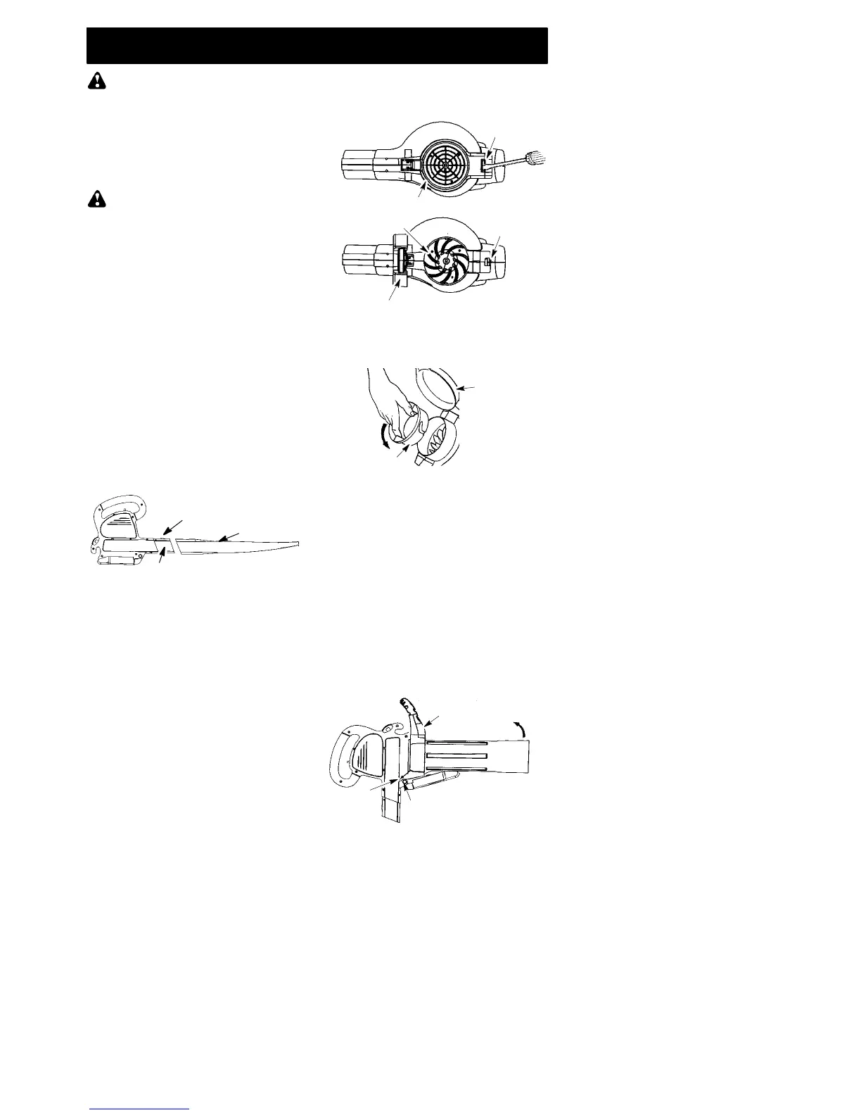
To attach blower tube:
1. Align the grooves on the blower tube
with the grooves on the blower outlet.
2. Pus h the blowertube onto the blower
outlet until it snaps into place (tube is
secured by red tube release button).
3. To remove the blower tube, press the
tube release button while pulling on
tube.
Blower Tube
Blower outlet
Tube Release Button
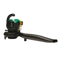
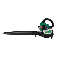
VACUUM ASSEMBLY
NOTE: Assembly instructions for using
your unit as a blower are explained inthe
previou s section.
If you have alrea dy assem bled your unit
for use as a bl ower, remove the blower
tube.
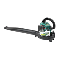
Remove the inlet restrictor
An inlet restrictor is used when using your
unit as a blower. This restrict or is not used
during vacuum use and must be removed
during assembly f or vacuum use.
NOTE: Be sure to keep the inlet re-
strictor for using your unit a s a blower.
1. Ensure unit i s stopped and ext ension
cord is unplugged.
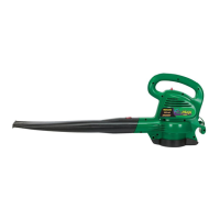
2. Open the inlet cover by inserting the
tip of a screwdriver into the latch a rea
on the blower unit. Gently tilt handle
of screwdriver toward the front of the
unit to release the latch while pulling
up on the vacuum inlet cover with
your other hand.
Vacuum Inlet Cover (closed)
Latch Area
Bottom view
of unit
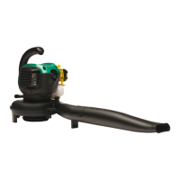
Vacuum Inlet Cover (opened)
Latch Area
Impeller
3. Turn the inlet restrictor counterclock-
wise and r emove it from the unit. Do
not cl ose the i nl et door. You will next
att ach the vacuum t ubes.
Inlet
Restrictor
Vacuum
Inlet Cover
Attaching the vacuum tubes
There are 2 vacu um tubes, an upper
tube and a lower tube. The upper tube
has a vacuum assist handle attached to
one end and is cut straight on both ends.
The upper tube attaches to the blower
unit. The lower tube has an angled end
that you point towa rd the ground during
vacuum use. The lower tube attaches to
the upper tube.
1. Ensure unit is stopped and exten-
sion cord is unplugged.
2. Whi l e holdi ng i nlet cover open, pl ace
th e hooks of the vacuum assist handle
on t h e ret aining posts of the unit.
3. Raise the tube unti l it is secured to the
blower unit by the red inlet cover latch.
Retaining Post
Vacuum Assist Handle
Upper