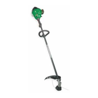
Air Filter
Air Filter Cover
MUFFLER AND SPARK ARREST-
ING SCREEN
_kWARNING: The muffler on this prod-
uct contains chemicals known to the State of
Cal_ornia to cause cancer
REPLACING THE LINE
As your unit is used, carbon deposits build up
on the muffler and spark arresting screen.
For norms} homeowner use, however, the
muffler and spark arresting screen wJ[I not re-
quire any service. After 50 hours of use, we
recommend that your muffler be serviced or
replaced by your authorized service dealer
REPLACE SPARK PLUG
Rep}ace the spark plug each year to ensure
the engine starts easier and runs better. Set
spark plug gap at 0.025 inch (06 mm). Igni-
tion timing is fixed and nonadjustable.
1. Twist, then pulI off spark plug boot
2. Remove spark plug from cylinder and
discard.
3. Replace with Champion RCJ-6Y spark
plug and tighten securely with a 3/4 inch
(19 ram) socket wrench.
4. Reinstall the spark plug boot.
1. Remove spoo_ by firmly puNing on tap
button.
2. Clean entire surface of hub and spool
3. Replace with a pre-wound spool, or cut two
lengths of 12-1/2 feet of 0.080" (2 mm) di-
ameter WEED EATER brand line
_kWARNING: Never use wire, rope,
stdng, etc.. which can break off and become a
dangerous missile.
4. Insert ends of the lines about 1/2 inch (f
cm) into the small holes on the inside of
spool
Spool "_ f_// l'//,JiJJ _ small
!/ Holes
Line exit holes Line in Notch
Hub
5. Wind the line evenly and tightly onto the
spool. Wind Jnthe direction of the arrows
found on the spool
6. Push the lines into the notches, leaving 3
to 5 inches (7 - 12 cm) unwound
7. Insert the lines into the the exit holes in
the hub as shown in the illustration.
8. Align the notches with the line exit holes.
g. Push spool into hub until it snaps into
p}ace
10. PulI the lines extending outside of the hub
to release the lines from the notches.
REPLACING THE CUTTING HEAD
1. Align hole in the dust cup with the hole Jn
the side of the gearbox by rotating the
dust cup.
2. Insert a small screwdriver into aligned
hotes. This will keep the shaft from turning
while removing and installing trimmer head.
3. While hoJding the screwdriver in position,
remove trimmer head by turning clock-
wlse.
4. Thread replacement tbmmer head onto
the shaft by turning counterclockwise.
Tighten until secure.
5. Remove the screwdriver
CARBURETOR ADJUSTMENT
_k WARNING: Keepothersawaywhen
making idle speed adjustments. The trimmer
head wilI be spinning during this procedure.
Wear your protective equipment and observe
a_lsafety precautions.
The carburetor has been carefully set at the
factory. Adjustments may be necessary if you
notice any of the following conditions:
• Engine will not idle when the throttle ts
released.