3
Keypad Operation and Parameter Setup:
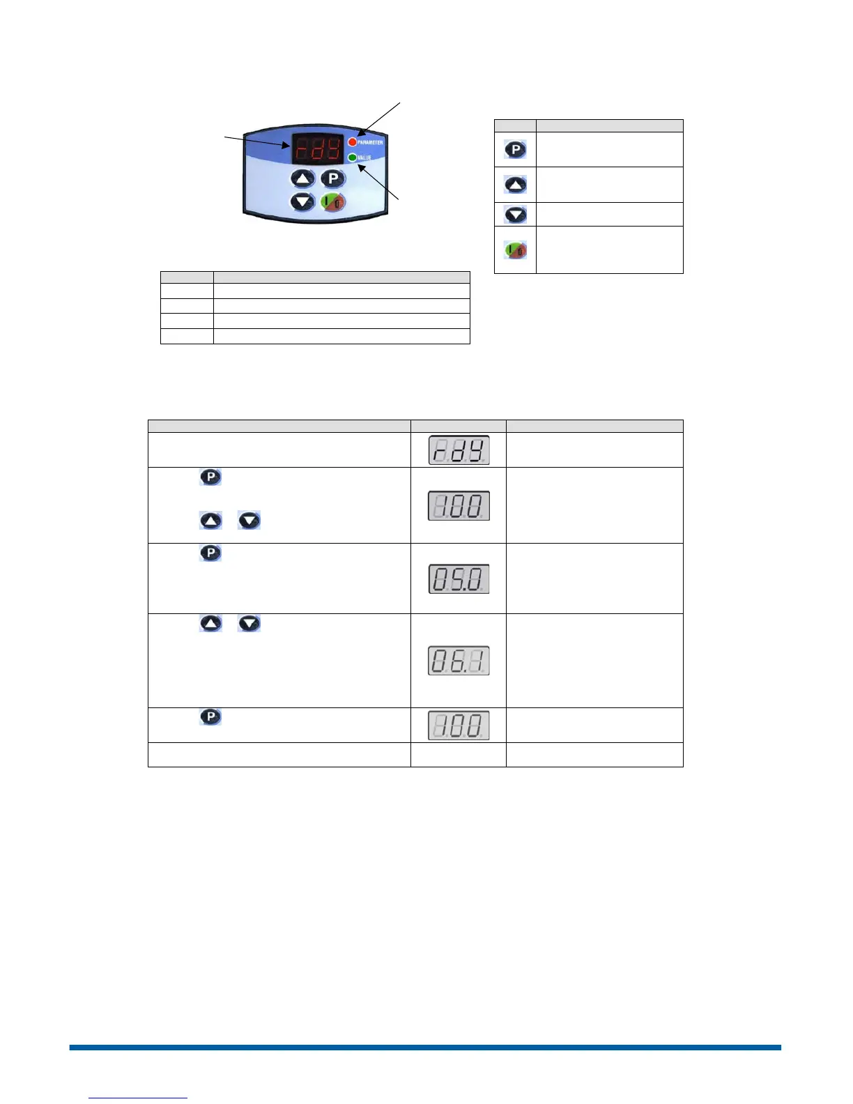
Figure 2 – Keypad Operation
Drive is ready to be enabled.
Power supply voltage too low for drive operation.
Drive in DC braking mode.
Drive is loading factory setting.
Note: Plus versions of the CFW10 have a
speed potentiometer on the lower right
side of the keypad which is used to
increase/decrease speed.
Description
Switche s the display between
parameter number and
content.
Increases Speed (frequency)
and Parameter
number/content
Decr eases Speed and
Parame ter number/content
Starts/Stops the drive via the
acceleration/deceleration
ramp and resets the drive
after a fault.
The CFW10 does not require parameter programming prior to start up and is ready to operate with the factory default
settings. A parameter example is given below to familiarize the user with parameter navigation, viewing, and
programming.
After power is applied to the drive, the display shows
the following message.
Drive is ready to be started.
Press the key to view parameter number. The red
LED on the keypad will light to indicate “parameter
number”.
Press the or arrow keys to select a
parameter.
Selec t the desired parameter. This
example uses parameter number
P100 (Acceleration Time).
Press the key to view the value of the parameter.
The green LED on the keypad will light to indicate
“parameter value”.
This is the num erical value
associated with the parameter. For
this example then P100=5.0
therefore the acceleration time is set
for 5 seconds.
Press the or arrow keys to change the
parameter value.
Set the new desired value. In this
example the acceleration time has
been increased to 6.1 seconds.
Note: To change parameter values
you must first set the access
parameter P000=5. Some para meter
changes require the drive be
stopped first.
Press the key to store the new value.
The new va lue for P100
(acceleratio n time) is stored in
memor y.
Repeat this procedure for other parameters that may
need to be changed.
LED Display –
indicates fault
codes, inverter
status, parameter
number and value.
Green LED –
When lit the
display indicates
the parameter
value.
Red LED –
When lit the
display indicates
the parameter
number.
Phone: 800.894.0412 - Fax: 888.723.4773 - Web: www.ctiautomation.net - Email: info@ctiautomation.net
 Loading...


