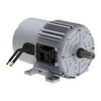
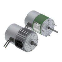
This document describes the WECM / Emerald eZA Three-Phase Motors, which are Electronically Commutated Motors (BLDC - Permanent Magnetic Synchronous Motor (Al)) designed for various industrial applications. This manual provides essential information for installation, operation, and maintenance of these motors.
Function Description
The WECM / Emerald eZA product is an Electronically Commutated Motor composed of a permanent magnet motor and a drive with features customized for commercial ventilation solutions. These motors are designed for efficient and reliable operation in various industrial settings, particularly those requiring precise speed control and robust performance. They are suitable for applications involving automation, energy transmission, and distribution.
Important Technical Specifications
The motors come with a nameplate that provides essential electrical and mechanical data. A typical model, WECM-EGM-L1, operates with a 3-phase input of 380V-480V at 50/60Hz, drawing 2.39-1.90A. The output is 3-phase 0-342V, 500-3000RPM, 10Amax. The drive code is WECM100EGT2P5IP5504212H01, and the software version is V1.19, firmware V1.13.
The manual provides detailed tables for maximum permissible thrust and axial loads for different mounting positions and speeds (1500 rpm, 1800 rpm, 3000 rpm, and 20000 rpm). For instance, at 1500 rpm, the horizontal pushing force is 0.90 kN, and the axial pushing force is 0.96 kN. At 20000 rpm, the horizontal pushing force is 1.31 kN, and the axial pushing force is 1.46 kN.
Inertia values for WECM frames IEC80 and IEC100 are also provided. For an IEC80 frame at 1500 rpm, the power is 0.12 kW with an inertia of 0.16 kgm². For an IEC100 frame at 3000 rpm, the power is 2.20 kW with an inertia of 0.47 kgm².
The drive supports various control signals, including common GND, PWM (10-95%), DC voltage (2-10V), DC current (4-20mA), RS485 communication, and 24VDC source. It features a DIP switch for settings like "On" and "Off" and rotation control (CW, CCW, Remote).
The maximum permissible cable length of the power supply must be within a maximum distance of 3 meters. Grounding must be carried out on the drive cover in an isolated manner. Measurements must be carried out under load, providing the air velocity over the motor as specified in the design.
The built-in power supplies have an output limit of:
- Three-Phase: 10 mA for the 10 VDC and 350 mA for the 24 VDC.
- The product can be permanently damaged if imposed signals out of the specification.
- Make sure that all unused conductors in control cable are insulated to avoid product malfunction or damage.
Usage Features
The motors are designed for ease of installation and operation. The manual emphasizes the importance of proper handling during shipment, storage, installation, operation, and maintenance to ensure safety and prevent damage.
Installation:
- The motor must always be positioned so the drain hole is at the lowest position to prevent water ingress.
- Motors supplied with rubber drain plugs leave the factory in the closed position and must be opened periodically to allow the exit of condensed water.
- For environments with high water condensation levels and motor with degree of protection IP56, the drain plugs must be mounted in open position.
- For motors with degree of protection IP56, IP65 or IP66, the drain plugs must remain at closed position, being opened only during the motor maintenance procedures.
- Motors installed outdoors or in the vertical position require the use of additional shelter to protect them from water.
- Connect the motor properly to the power supply by means of safe and permanent contacts, always considering the data informed on the nameplate, such as rated voltage, wiring diagram, drive inputs, among others.
- For power cables, switching and protected devices dimensioning, consider the rated motor current, the service factor, and the cable length, among others.
- For motors without terminal block, insulate the motor terminal cables by using insulating materials that are compatible with the insulation class informed on the nameplate.
- The minimum insulation distance between the non-insulated live parts themselves and between live parts and the grounding must meet the applicable standards and regulations for each country.
- Make the power connections following nameplate indication: Power input: L1, L2 and L3 terminals; Protective earth: PE - green screw.
- If using the connect the optional external harmonic filter (passive PFC) in series to the line conductor.
- WECM / Emerald eZA motor line is intended to be used as a part of an end-product and thus is not an independently used machine. All cables of this product need to be internally insulated into the enclosure of the final product.
Speed Adjustment:
The product speed can be changed by local adjust (buttons) or remote adjust (control inputs).
- To select between local or remote speed adjust: Remove the lid from the back side of the drive cover; Use the DIP switch identified as L / R to select between local (L) or remote (R); Reinstall the lid to the back side of the drive cover after the adjust.
- The speed can be adjusted using the external speed controller (see item 6.5).
- The product will turn off if imposed signals lower than 2 VDC, 4 mA DC or 10%.
- The speed can be adjusted by: DC voltage: 2 to 10 VDC [tolerance: ± 10%], DC current: 4 to 20 mA DC [tolerance: ± 10%], Frequency duty-cycle / PWM: 10 to 95% [tolerance: ± 10%], Frequency: 10 to 24 Vpp [tolerance: ± 5% / + 10%], Frequency: 80 Hz [tolerance: ± 2.5% / + 2.5%].
- When available, using the RS485 serial communication (see item 6.7).
Modbus Communication:
The device supports Modbus RTU communication, allowing for remote control and monitoring. This includes setting baud rate, parity, and stop bits. The default Modbus address is 85.
Maintenance Features
Regular maintenance is crucial for the longevity and reliable operation of WECM / Emerald eZA motors.
General Maintenance:
- Before any service is performed, ensure that the motor is at a standstill, disconnected from the power supply, and protected against accidental energization.
- Even when the motor is stopped, dangerous voltages may be present in space heater terminals.
- For motors with permanent magnet rotor (WECM and Emerald eZA), the motor assembly and disassembly require the use of power devices due to the attracting or repelling forces that occur between metallic parts. This work must only be performed by a WEG authorized service center specifically trained for such an operation.
- People with pacemakers cannot handle these motors. The permanent magnets can also cause disturbances or damages to other electric equipment and components during maintenance.
- Motor disassembly during the warranty period must be performed by a WEG authorized service center only.
- Regularly inspect the operation of the motor, according to its application, and ensure a free air flow. Inspect the seals, the fastening bolts, the bearings, the vibration and noise levels, the drain operation, etc. The lubrication interval is specified on the motor nameplate.
Troubleshooting:
The manual includes a table for blinking behavior according to fault type, indicating the fault and corresponding on/off times. For example, an "Under voltage" fault will cause the LED to blink for 0.1s on and 0.1s off.
Firmware Update:
The device supports firmware updates via a USB to 485 converter connected to a PC. This process involves specific steps for communication setup and software interaction.
Serial Configuration:
The serial configuration can be reset to factory defaults by removing the lid, pressing and holding local tact buttons SW1 and SW2 for 5 seconds, and then observing LED #2 blinking 5 times to confirm the event. The default settings for Modbus control are address 0x55 (85), baud rate 19200 bits/s, start bit 1, data bits 8, parity even, and stop bit 1.
Product Protection and Fault Diagnosis:
WECM / Emerald eZA products have the following electronic protections:
- Input under voltage protection.
- Input over voltage protection.
- Input over load protection.
- Locked rotor protection.
- Over temperature protection.
- Output overcurrent / short-circuit protection.
- WECM / Emerald eZA products have LED's in the opening on the back side to indicate the solution status and to help in the fault diagnosis.
- Off: Stopped (LED #1 Off, LED #2 Off)
- On: Running (LED #1 On, LED #2 Blinking (1 Hz))
- On: Fault (LED #1 Blinking according fault (check Table 9), LED #2 Blinking (1 Hz))
This comprehensive manual ensures that users can effectively install, operate, and maintain their WECM / Emerald eZA Three-Phase Motors, maximizing their performance and lifespan.