www.weg.net
11239449 Installation, operation and maintenance manual – Squirrel cage motor – W Line - Horizontal and vertical l 21
Figure 4.2: Connection of the megohmmeter to separate phases
If the total winding measurement presents a value below
the recommended, the neutral connections must be
opened and the insulation resistance of each phase must
be measured separately.
TTENTION
Much higher values may be frequently
obtained from motors in operation for long
periods of time. Comparison with values
obtained in previous tests on the same motor
- under similar load, temperature and
humidity conditions – may be an excellent
parameter to evaluate the winding insulation
conditions, instead of using the value
obtained in a single test as the basis.
Significant or sudden reductions are
considered suspicious.
4.4.4 Additional Information
TTENTION
fter measuring the insulation resistance,
ground the tested winding in order to
discharge it.
The testing voltage to measure the insulation
resistance of the space heater must be 500
dc and for the other accessories, 100 Vdc.
It is not recommended to measure the
insulation resistance of thermal protectors.
4.4.5 Polarization Index
The polarization index is defined by the ratio between the
insulation resistance measured in 10 minutes and the
insulation resistance measured in 1 minute. This
measurement procedure is always carried out at relatively
constant temperatures.
The polarization index allows the assessment of the motor
insulation conditions.
DANGER
In order to avoid accidents, the winding must
be grounded immediately after measuring the
insulation resistance.
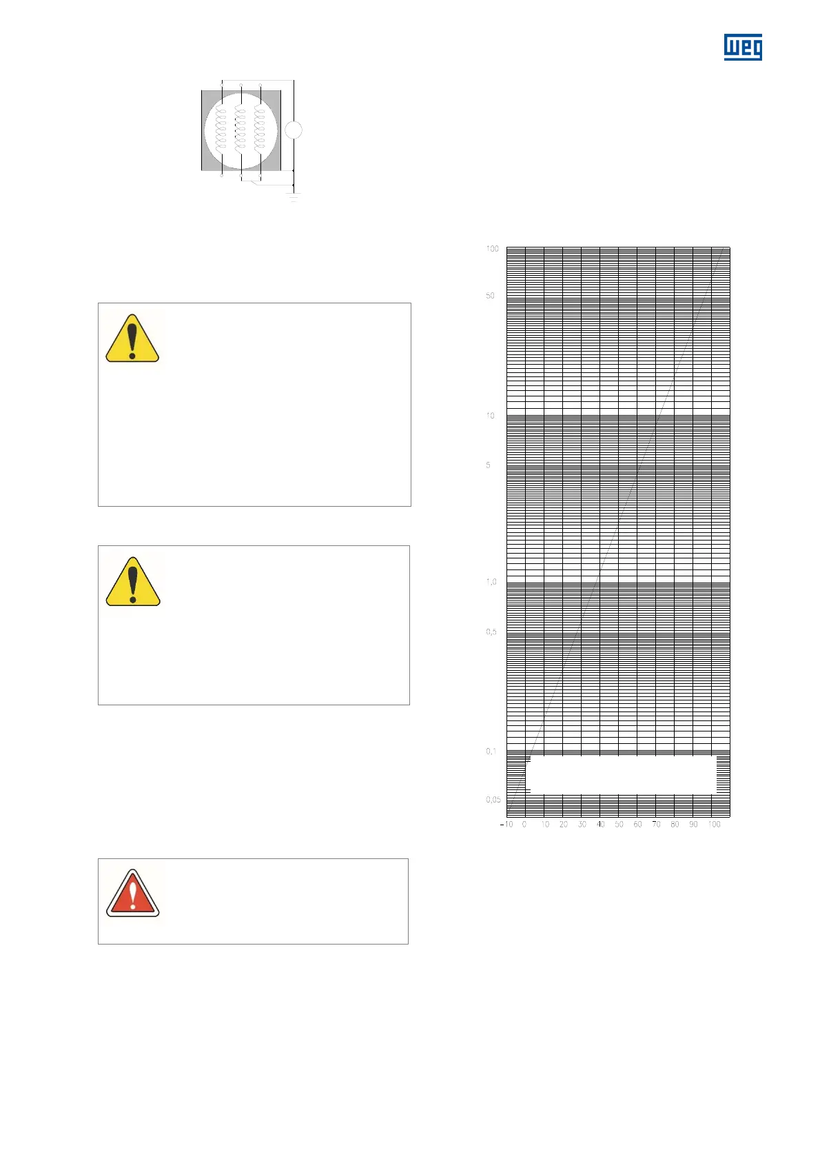
4.4.6 Conversion of the measured values
The insulation resistance must be measured at 40°C. If the
measurement is performed at a different temperature, it is
necessary to correct the reading to 40°C by using a curve
of the insulation resistance variation as a function of the
temperature, obtained at the motor itself. If this curve is
not available, the approximate correction provided by the
curve in Figure 4.3, according to NBR 5383 / IEEE43
standard, may be used.
Figure 4.3: Insulation resistance variation coefficient according to
the temperature
Winding temperature ºC
R
40ºC
= Rt x Kt
40ºC
o convert the insulation resistance
measured (Rt) for 40 ºC, multiply by the
temperature coefficient (Kt)
Coefficient of insulation resistance variation Kt
40ºC
M