www.weg.net
11239449 Installation, operation and maintenance manual – Squirrel cage motor – W Line - Horizontal and vertical l 27
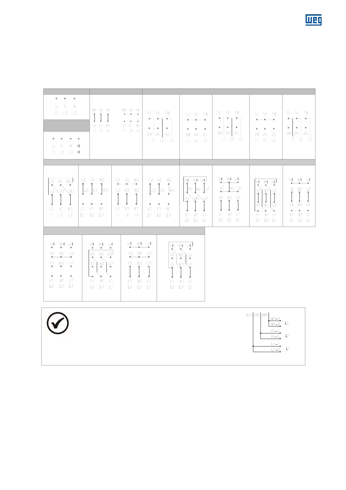
4.7.2 Connection diagrams
4.7.2.1 Connection diagrams according to IEC60034-8
The following connection diagrams show the terminal identification in the terminal box and the possible connections for the
motors.
4.7.2.1.1 Stator connection diagrams
3 TERMINALS 6 TERMINALS 6 TERMINALS - DAHLANDER
Δ Y
Δ
LOWER SPEED
YY
HIGHER
SPEED
Y
LOWER SPEED
YY
LOWER
SPEED
Δ
HIGHER
SPEED
3 TERMINALS +
NEUTRAL
9 TERMINALS 12 TERMINALS
ΔΔ
Δ
YY
Y
ΔΔ
YY
Δ
Y
12 TERMINALS - (part winding)
FOR Y START
FOR Δ START
Y FOR START
ONLY
FOR RATED SPEED
NOTE
When two or more motor connecting cables are used in parallel in
order to divide the electric current, the identification of these cables is
made with an additional suffix separated by a hyphen, according to
Figure
4.5.
Figure 4.5: Parallel connections