QUICK START GUIDE
USB
USB USB 2.0
Connector Pinouts
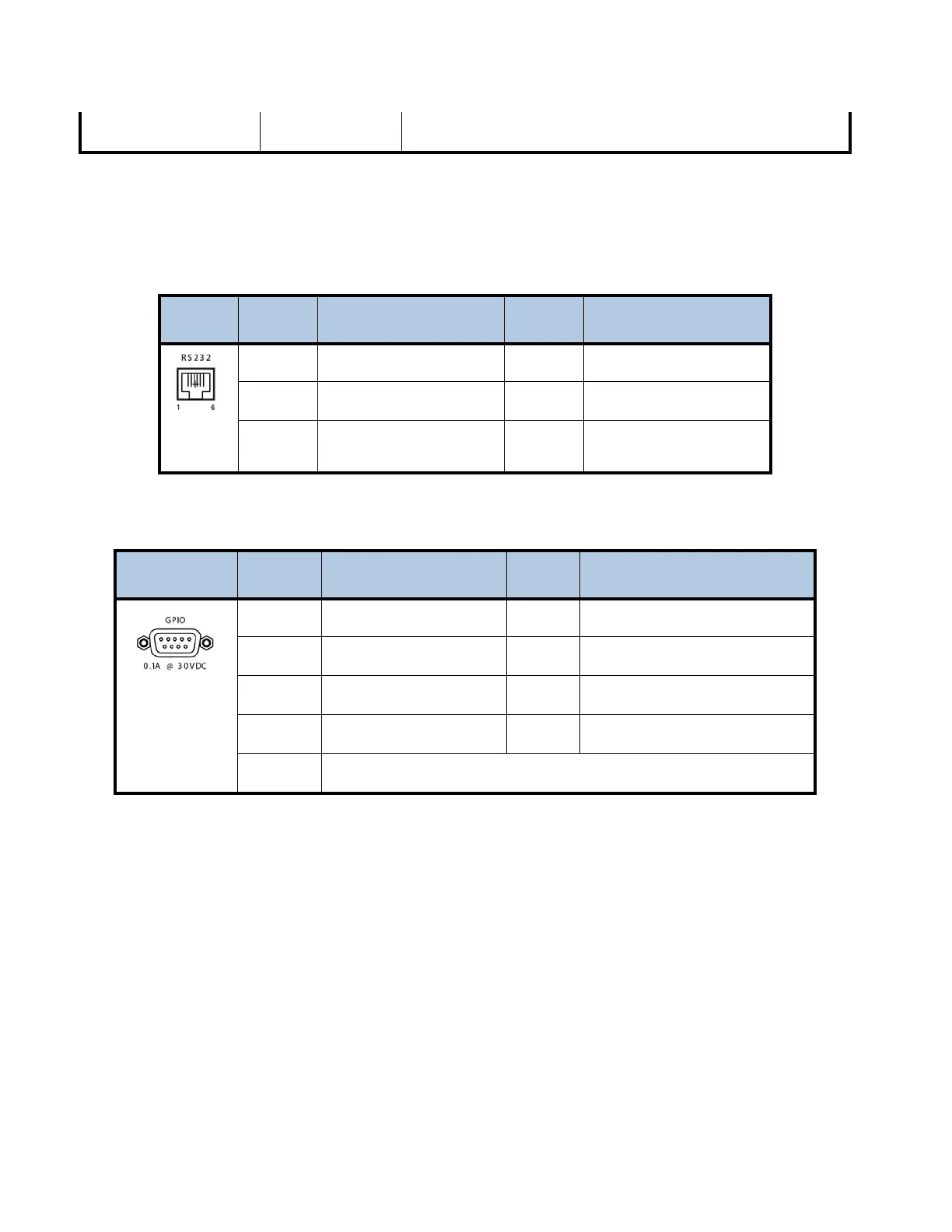
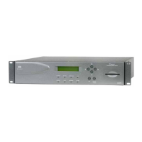
The tables below describe pinout connections for the RJ-12 and DB-9 connector.
Serial Port RS-232 Pinouts
Image Pin Input Output Description Pin Input Output Description
1
No Connection
4
No Connection
2
TX Data Output
5
Ground
3
RX Data Input
6
+5V DC
GPIO Pinouts
Image Pin Input Output Description Pin Input Output Description
1
Alarm relay Common
6
Alarm relay Normally Closed
2
Alarm relay Normally Open
7
User relay Normally Closed
3
User relay Common
8
User relay Normally Open
4
No Connection
9
Ground
5
GPIO Input
AUTION: Do not connect RJ-12 directly to phone line. Equipment damage may result. C
4 800092-02 Rev. C www.wegener.com