12
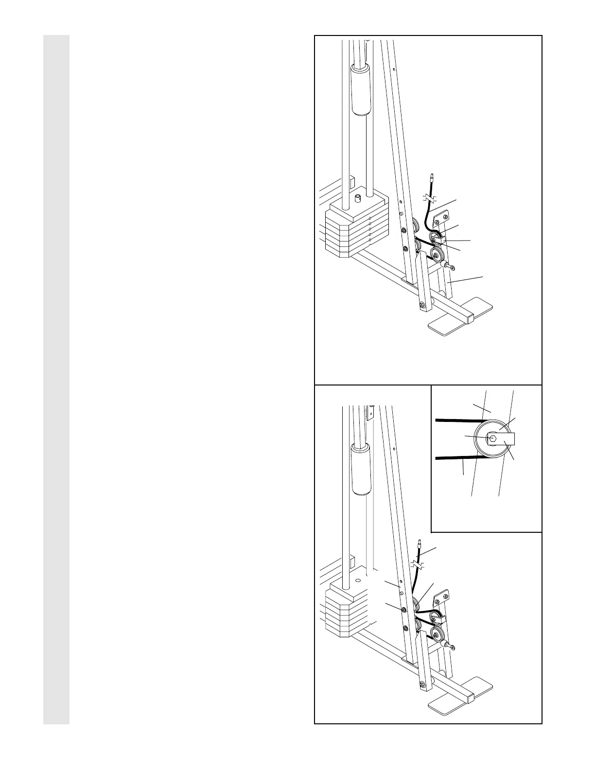
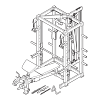
21. Route the Short Cable (58) around the 3 1/2”
Pulley (15) attached to the upper hole in the
Press Frame (17). Be sure that the Cable
Trap (66) is turned to hold the Cable in
place and that the Cable is routed around
the Pulley as shown. Tighten the M10 Nylon
Locknut (21) and the M10 x 80mm Bolt (not
shown).
22. Route the Short Cable (58) around the 3 1/2”
Pulley (15) attached to the upper hole in the
Front Upright (42). See the inset drawing.
Be sure that the Cable Trap (66) is turned
to hold the Cable in place and that the
Cable is routed around the Pulley as
shown. Tighten the M10 Nylon Locknut (21)
and the M10 x 95mm Bolt (71).
22
21
CABLE ASSEMBLY
58
15
66
21
17
71
58
Inset shows view
from other side
42
66
15
42
58
15
21