6 Commissioning | Commissioning with Automation Studio (POWERLINK)
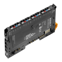
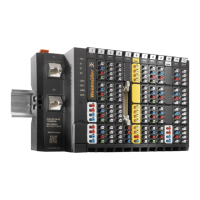
34 2547720000/03/09.2019Manual Communication module UR20-4COM-IO-LINK
Restarting the coupler
▶ In the Physical View, right-click the module.
▶ Click Configuration in the context menu.
The list of all parameters is displayed.
▶ Determine the required process data length of the
IO-Link master, by adding the length of the input data and
output data of the connected IO-Link devices.
▶ Set the “Process data length input” parameter of the
IO-Link master to the required value.
▶ Set the “Process data length input” parameter of the
IO-Link master to the required value.
All settings only take effect once they have been
loaded into the component.
Parameterising IO-Link port with Automation Studio
The IO-Link ports are parameterised via the parameters of
the IO-Link master. An overview of all parameters can be
found in section 4.6.
▶ In the Physical View, right-click the module.
▶ In the context menu, click Configuration.
The list of all parameters is displayed.
Editing module parameters
▶ Click the parameter that you would like to change and
amend the setting as required.
▶ Use this method to edit all of the parameters that you
would like to change.
All settings only take effect once they have been
loaded into the component.
Integrating IO-Link device with Automation Studio
An IO-Link device is integrated using the appropriate parame-
terisation of the associated IO-Link port.
▶ In the Physical View, right-click the module.
▶ In the context menu, click Configuration.
The list of all parameters is displayed.
▶ Set the “Operating mode” parameter of the IO-Link port to
the value “IO-Link”.
▶ Set the “Process data length input” parameter of the
IO-Link port to the value “auto (default)”.
▶ Set the “Process data length output” parameter of the
IO-Link port to the value “auto (default)”.
▶ Change the other parameters as required.
All settings only take effect once they have been
loaded into the component.