Do you have a question about the Weidmüller UR20-4COM-IO-LINK and is the answer not in the manual?
Describes warning symbols and safety notices used in the manual.
Lists related manuals and resources for further information.
Explains data structure, mapping, and standard formats.
Lists the firmware releases of the couplers described.
General safety precautions for electricians and personnel.
Requirements for equipment installation environment.
Guidelines for electrical protection and fuses.
Proper grounding procedures for modules.
Describes the module's purpose and application.
Safety guidelines and requirements for operating in hazardous areas.
Compliance information and software licenses.
Explains IO-Link as a communication protocol.
Defines IO-Link master and device roles.
Details how IO-Link communication operates.
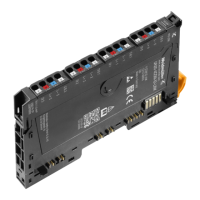
Provides an overview of the module and its order number.
Identifies and labels the module's external components.
Lists the components of the I/O module.
Shows wiring diagrams and pin assignments.
Explains the meaning of LED statuses for diagnostics.
Illustrates the internal structure and signal flow.
Lists key specifications, ratings, and dimensions.
Details configurable module parameters and their options.
Explains the function of the operating mode setting.
Explains how port cycle time is determined.
Defines the cycle time for IO-Link ports.
Describes checking IO-Link device identity.
Explains the Data Storage activation function.
Describes enabling channel diagnostics.
Defines the size of process input data.
Defines the size of process output data.
Guides the connection of IO-Link devices to the module.
Specific connection details for IO-Link Class A ports.
Specific connection details for IO-Link Class B ports.
Connects non-IO-Link devices to the module.
Shows sensor connection via C/Q.
Shows sensor connection via DI.
Shows load connection via C/Q.
Lists prerequisites that must be met before commissioning.
Explains the need for GSD/ESI/EDS/XDD files for configuration.
Steps to update firmware of the fieldbus coupler and module.
Steps to configure the IO-Link master.
How to parameterize IO-Link ports.
Process for configuring IO-Link devices in real-time.
Transferring configurations to the u-remote station.
Commissioning process using SIMATIC Manager.
Installing GSD files for SIMATIC Manager.
Choosing the correct GSDML file.
Selecting the module variant based on data length.
Parameterizing IO-Link ports within SIMATIC Manager.
Modifying module parameters within SIMATIC Manager.
Commissioning process using TIA Portal.
Installing GSD files for TIA Portal.
Choosing the correct GSDML file in TIA Portal.
Selecting module variant based on data length in TIA Portal.
Parameterizing IO-Link ports within TIA Portal.
Modifying module parameters within TIA Portal.
Commissioning process using TwinCAT.
Installing ESI files for TwinCAT.
Setting up the IO-Link master with TwinCAT.
Parameterizing IO-Link ports in TwinCAT.
Modifying module parameters in TwinCAT.
Commissioning process using Studio 5000.
Installing EDS files for Studio 5000.
Setting up the IO-Link master with Studio 5000.
Modifying module parameters in Studio 5000.
Adjusting the input data length for the module.
Adjusting the output data length for the module.
Saving the module parameters.
Procedure to restart the coupler.
Setting the coupler's process data length.
Parameterizing IO-Link ports for Ethernet/IP.
Device integration for Ethernet/IP.
Commissioning process using Automation Studio.
Installing XDD files for Automation Studio.
Choosing XDD files for import.
Setting up the IO-Link master with Automation Studio.
Parameterizing IO-Link ports in Automation Studio.
Modifying module parameters in Automation Studio.
Device integration with Automation Studio.
Accessing and manipulating data objects on IO-Link devices.
Explains the protocol for acyclic data access.
Sequence for writing data to an IO-Link device.
Sequence for reading data from an IO-Link device.
Addressing schemes for acyclic data access.
Addressing for acyclic write requests.
Parameters for IO-Link call requests.
Addressing for acyclic read responses.
Parameters for IO-Link call responses.
Retrieving information about connected IO-Link devices.
Requesting specific device information.
Response format for device information.
Obtaining the mapping of process data.
Requesting process data mapping.
Response format for process data mapping.
Retrieving events from the event queue.
Requesting the event queue.
Response format for the event queue.
Details of the IO_LINK_CALL function block.
Input parameters for the IO_LINK_CALL function block.
Output parameters for the IO_LINK_CALL function block.
TIA portal specific variable mapping for IO_LINK_DEVICE.
Using the IO_LINK_DEVICE block in STEP7.
Explanation of I&M (Installation and Maintenance) functions.
Directory for IOL-M related I&M functions.
Basic I&M functions.
Procedure for sending upload requests.
Overview of the u-remote IO-Link configuration tool.
Steps to install the IO-Link configurator software.
Installing the software via an installer.
Using the portable version without installation.
How to use the IO-Link configurator.
Accessing the configurator's initial start page.
Method to launch the start page.
Overview of IO-Link ports within the tool.
Display of IO-Link ports in online mode.
Detailed view of a device within the configuration tool.
Describes the elements shown in the detailed device view.
How to access context menus within the tool.
Steps to create a new project in the configurator.
Steps to save a project within the configurator.
Steps to open an existing project in the configurator.
Changing the configurator's user interface language.
Accessing the IODDfinder to download device descriptions.
Direct link to the IODDfinder website.
Exporting configuration files from the configurator.
How to edit IO-Link device configurations.
Process of assigning IO-Link devices to ports.
Adding device description files (IODD) to the configurator.
Selecting different device types for a port.
Unassigning IO-Link devices from ports.
Modifying parameters of an IO-Link device.
Setting parameters for an IO-Link device.
Calculating required process data length for configurations.
Editing device configurations in real-time.
Troubleshooting faulty parameters in configurations.
Identifying parameter errors in the device.
Navigating directly to parameter error locations.
Establishing connection for online editing.
Enabling IO-Link ports for operation.
Disabling IO-Link ports.
Verifying the identity of connected IO-Link devices.
Obtaining device descriptions for connected devices.
Retrieving parameters from IO-Link devices.
Updating individual parameters.
Writing device parameters to IO-Link devices.
Showing process data tables.
Showing diagnostic information.
Explains how process data is mapped to module bytes.
Illustrates data mapping with a specific configuration.
Details the structure and meaning of input data bytes.
Table showing input data bytes and their descriptions.
Details the structure and meaning of output data bytes.
Table showing output data bytes and their descriptions.
Shows data width variations based on fieldbus couplers.
Data widths for the PB-DP coupler.
Data widths for the PN-IRT coupler.
Data widths for the EC coupler.
Data widths for the PL coupler.
Data widths for MOD-TCP couplers.
Data widths for the EIP coupler.
Data widths for the DN coupler.
Data widths for the CAN coupler.
Explains how to access and interpret module diagnostic data.
Table detailing diagnostic data bits and their meanings.
Lists event codes for IO-Link masters.
Interpreting LED statuses for troubleshooting and diagnostics.
Step-by-step instructions for safely disassembling modules.
Guidelines for the proper disposal of electronic modules.
| Brand | Weidmüller |
|---|---|
| Model | UR20-4COM-IO-LINK |
| Category | I/O Systems |
| Language | English |