11
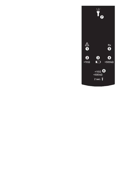
5.0 Control Elements and Connections
1. LED indicates high (dangerous) voltage
from 50V up to 400V
2. Indicate measurement range <10 Ω
3. Indicate low battery
4. Indication measurement range <500kΩ
5. Rx LED is used for indication of continuity
for selected operation mode
6. Button for dierent ranges and torch light
7. Torch light
6.0 Using of device
• Continuity tester can be turned on with
short press on pushbutton (7). The con-
tinuity tester turns on automatically if
continuity <500kΩ is detected between
probes. After turn on, Continuity Tester operates in <500kΩ-
operating mode by default.
• Short press on pushbutton switches between operating modes:
<500kΩ or <10Ω. <500kΩ -> <10Ω -> <500kΩ.
• Long press on pushbutton >2s turns on Torch light. Torch light turns
o automatically 30s after activation, or by second Long press >2s
on pushbutton.
• Long press on pushbutton >6s turn o device.
• Self-test of device can be activated with shorting of tips (probes)
while device is turned o.
• Device indicates Continuity by Rx LED and beeps if resistance be-
tween tips is less than 500kΩ for <500kΩ-range, and if resistance is
less than 10Ω for <10Ω-range.
• Continuity tester is intended for use on non-energized environment.
The ELV LED is used to signalize dangerous voltage. If ELV LED
turns on during test, testing must be stopped.
• If Low Battery LED turns on, 2xAAA batteries needs to be replaced.