Primary/secondary piping to boiler
Using primary/secondary piping will provide the most effi cient
and reliable operation of the boiler and the heating system.
1. Use information beginning on page 47 to size pump for proper
fl ow through the ECO boiler.
2. Reference suggested piping layouts on pages 53 - 55 .
Some installations can be piped in numerous other ways
that will work equally as well as the suggestions here.
Verify the application will work:
For systems requiring a higher flow than that
recommended in Figure 47 − DO NOT use a
direct connect piping layout. Design system using
a primary/secondary piping layout using guidelines
starting on page 47 .
Systems zoning with circulators must use primary/
secondary piping layout using guidelines starting
on page 47 .
Check system fl ow rate
To determine whether direct connection will provide suitable fl ow
for the intended application, refer to Figure 41.
4. The minimum temperature drop across the heat exchanger
is 20°F. Using fl ow rates higher than the maximum listed in
Figure 41 is NOT RECOMMENDED.
5. Design zoning to ensure minimum fl ow rate is maintained
under any call for heat condition that could see full input
rate (High Fire).
Systems using a modulating pump may operate
below the minimum fl ow rates listed in Figure 47
only if the boiler is operating at a reduced fi ring rate
(low fi re) when doing so. A pump that modulates
based on the system Delta T (T) would provide such
operation assurance by varying fl ow with fi ring rate.
Use a primary/secondary piping layout if the total fl ow through
the ECO’s heat exchanger will be higher than the maximum listed
in Figure 47 .
Check system pipe design
Only systems with a single system pump zoned with zone valves
may use the direct connect system piping methods shown here.
Any system zoned with zone valves must include a
by-pass pressure regulator. Failure to comply may
reduce pump life.
Expansion tank location
Figure 48 and Figure 50 show typical installation of the system
expansion tank. It is highly recommended that you locate the air
separator and expansion tank as shown in the suggested piping
drawings on page 47 and page 48 .
Ensure that the expansion tank size will handle boiler and
system water volume and temperature. See tank manufacturer’s
instructions and ratings for details. Additional tanks may be added
to the system if needed to handle the expansion. These tanks may
be installed by connecting to tees in the system piping.
Undersized expansion tanks cause system water to
be lost from the relief valve and makeup water to be
added through the fi ll valve. Eventual boiler failure
can result due to excessive make-up water addition.
Always locate the cold-water fi ll connection at the
expansion tank. Never locate this elsewhere.
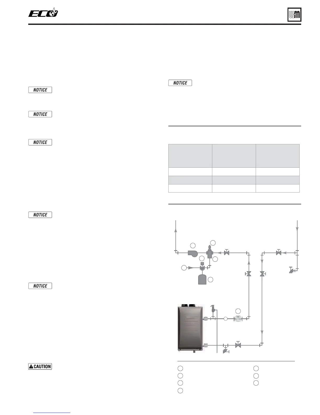
Diaphragm- or bladder-type tank:
Refer to Figure 48 for suggested piping when using a diaphragm-
or bladder-type expansion tank.
Install an automatic air vent on top of the air separator, per
separator manufacturer’s instructions.
Diaphragm- or bladder-type expansion tank—
Control fill pressure with the tank air charge
pressure. Always check pressure and charge tank
with tank removed from system to be sure reading
is accurate. Boiler relief valve is set for 30 PSIG.
Operating pressure of system, after temperature
expansion above cold fi ll pressure, should not exceed
24 PSIG to avoid weeping of relief valve.
Figure 47 Maximum and minimum fl ow rates through
boiler heat exchanger
ECO
Model
MAXIMUM
fl ow rate
through
boiler
MINIMUM
fl ow rate
through
boiler
70
6.5 GPM 3.0 GPM
110
10.0 GPM 5.0 GPM
155
14.5 GPM 7.0 GPM
Figure 48 Piping to diaphragm- (or bladder-) type
expansion tank
Direct Connect System Piping
Part number 550-142-190/1218
43
SERIES 2 GAS-FIRED WATER BOILER — Boiler Manual
4ZTUFN
SFUVSO
4ZTUFN
TVQQMZ
'JMMWBMWFUZQJDBM
.BLFVQXBUFSTVQQMZ
"JSTFQBSBUPS
4ZTUFNDJSDVMBUPS
"VUPNBUJDBJSWFOU
%JBQISBHNUZQFFYQBOTJPOUBOL
&$0
-PX8BUFS$VU0GG
*GVTFE
#PJMFS
PVUMFU
#PJMFS
SFUVSO
 Loading...