DIRECT VENT
— Sidewall with W-M vent/air plate
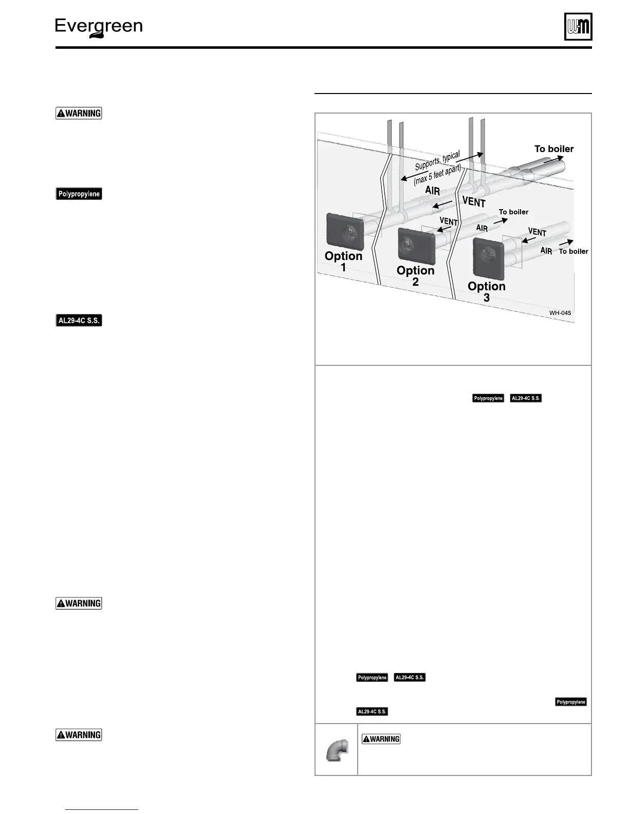
&IGURE ).34!,,!4)/. — W-M sidewall vent/air plate
Part number 550-100-131/0715
– 25 –
™
GAS-FIRED WATER BOILER — Boiler Manual
!LLOWABLEVENTAIRPIPEMATERIALSLENGTHS
Use only the vent materials and kits listed in
Figure 21, page 19. Provide pipe adapters if
specified.
1. Locate the termination such that the total air pip-
ing and vent piping from the boiler to the termina-
tion will not exceed the maximum length given in
Figure 20, page 18.
For polypropylene applications, comply with
any additional requirements in the vent system
manufacturer’s instructions. Provide 4” PVC-
to-PP transition pieces at the boiler vent and
air connections. PP adapter must have smooth,
straight section of pipe to insert in to the boiler
vent and air connections and must fit and seal
tightly. PP adapters with their own seal which
would interfere with the internal seal of the
boiler vent or air connections must not be
used. Refer to page 115 for a list of compliant
adapters. Install a locking collar at every joint.
For AL29-4C vent pipe applications, comply
with any additional requirements in the vent
system manufacturer’s instructions. Provide 4”
PVC transition pieces at the boiler and at the
vent and air terminations. (The air pipe must
be PVC or CPVC.)
2. For 4” to 3” transitions, must use appropriate vent
material. For polypropylene or stainless steel must use
approved suppliers transitions (EVG 220 only).
$ETERMINETERMINATIONLOCATION
1. Wall penetration thickness between 0” to 24”.
2. The vent/air cap must be installed as shown in
Figure 30, page 26.
3. The termination must comply with clearances and limi-
tations shown in Figure 22, page 21.
4. Locate the termination so it is not likely to be damaged
by foreign objects, such as stones or balls, or subject to
buildup of leaves or sediment.
-ULTIPLEVENTAIRTERMINATIONSORTERMINATION
ADJACENTTOOTHERAPPLIANCETERMINATIONS
1. When terminating multiple Evergreen
TM
boilers, ter-
minate each vent/air connection as described in this
manual.
All vent pipes and air inlets must terminate at
the same height to avoid possibility of severe
personal injury, death or substantial property
damage.
2. Place wall penetrations to obtain minimum clearance
as shown in for U. S. installations. For Canadian instal-
lations, provide clearances required by CSA B149.1 or
B149.2 Installation Code and a ULC S636 compliant
vent kit.
3. The air inlet of a Evergreen
TM
boiler is part of a direct
vent connection. It is not classified as a forced air intake
with regard to spacing from adjacent boiler vents.
For terminations of other appliances, provide
at least the clearance shown . The installation
must also comply with the manual for the
other appliances.
6ENTAIRPIPESANDVENTAIRCANBEORIENTEDASOPTION
OR$/./4MOUNTWITHPLATEVERTICALANDVENTOUTLETDOWN
3TEP Read and follow all instructions in this manual. $/./4
PROCEEDWITHVENTAIRINSTALLATIONUNTILYOUHAVEREAD
PAGETHROUGHPAGE
See notices
at left.
3TEP Install the boiler in a location that allows proper routing of all
vent and air piping to the selected sidewall location.
3TEPMake sure the selected sidewall termination location complies
with Figure 22, page 21. (Multiple boiler sidewall plates must
also comply with Figure 25, page 24.)
3TEPUse only the vent materials listed in Figure 21, page 19. Provide
pipe adapters where required.
3TEPVent piping and air piping lengths must not exceed the values
shown in Figure 20, page 18.
3TEPEnsure proper clearance above grade or snowline. Keep vents/
air intake area clear of accumulating snow.
3TEPPrepare the sidewall penetrations and secure the sidewall plates
as instructed in this section. See “Install Weil-McLain vent/air
cap” on page 26.
3TEPThe Weil-McLain plate termination must be installed before
piping from the boiler to the termination.
3TEPInstall vent and air piping between the boiler and the vent/air
termination plate. Slope horizontal piping downward toward
the boiler at least 1/4 inch per foot. See page 34 for general
guidelines.
3TEPInstall pipe supports every 5 feet on both the horizontal and
vertical runs, or per vent pipe manufacturer’s instructions.
See notices at left.
3TEPInstall a hanger support within 6 inches of any upturn in the
piping, or per vent pipe manufacturer’s instructions.
See notices at left.
53%37%%0%,"/73&/2!,,6%.4!.$
!)20)0).' — DO NOT use short radius elbows
for vent or air piping. Boiler performance could be
affected.
 Loading...