Tech. Dok. / WNW 850 02 / 02.2005.A / © MICHAEL WEINIG AG Weinig Tools 4-15
Hydraulic clamping
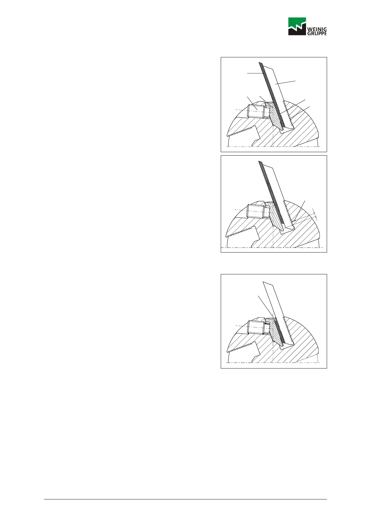
4.3.6 DoubleBack
Two-part cutter comprising a tip (1) and carrier plate (2).
Carrier plate and tip are positively connected via a
serration (3). Due to its special back serration (4) the
carrier plate (2) can only be fitted in the tool in one
position and is held securely. Carrier plate and tip are
clamped in the tool by means of pressure screws (5)
acting on a clamping ledge (6).
The mark (7) indicates the maximum adjustment (a) of
the tip in relation to the carrier plate. The bottom of the
tip must not be displaced beyond this mark for safety
reasons, otherwise the stability of the entire system will
be jeopardized.
4.3.7 Grinding DoubleBack cutters
The carrier plates must first be profiled without the tips.
Blind lugs (8) must be fitted in order to grind the carrier
plates. They are only ground once. The lowest point in
the profile is ground as close to the tool body as
possible. Use a tracing pin dia. 3 mm and grinding
wheel 4 mm wide for grinding. This ensures that the
profile in the carrier plate is slightly wider than the profile
in the tip.
Remove the blind lug after grinding the carrier plate and
install the tip in the bottom serration. Use a diamond
wheel to grind the carbide tips.
The diameter of the tracing pin must correspond with the
width of the grinding wheel. After profiling, the tip must
not protrude more than max. 5 mm in relation to the
carrier plate. If the carrier plate is reached when the tip
is resharpened, the tip must be moved forwards one
space. The tip must be replaced and a new one fitted
when the maximum adjustment has been reached.
DOKW0028
1
2
3
4
56
DOKW0029
7
a
DOKW0082
8
 Loading...