Heating System Tempura | Système de chauffage Tempura – Instructions for assembly, maintenance and use |
Notice de montage, instructions d’entretien et d’utilisation Version | Version 05.08.2019
Reserve technical changes | Sous réserve de modifications techniques Item no. | N° art. 115727-0000 Page | Page 10/20
Notice de montageAssembly instructions
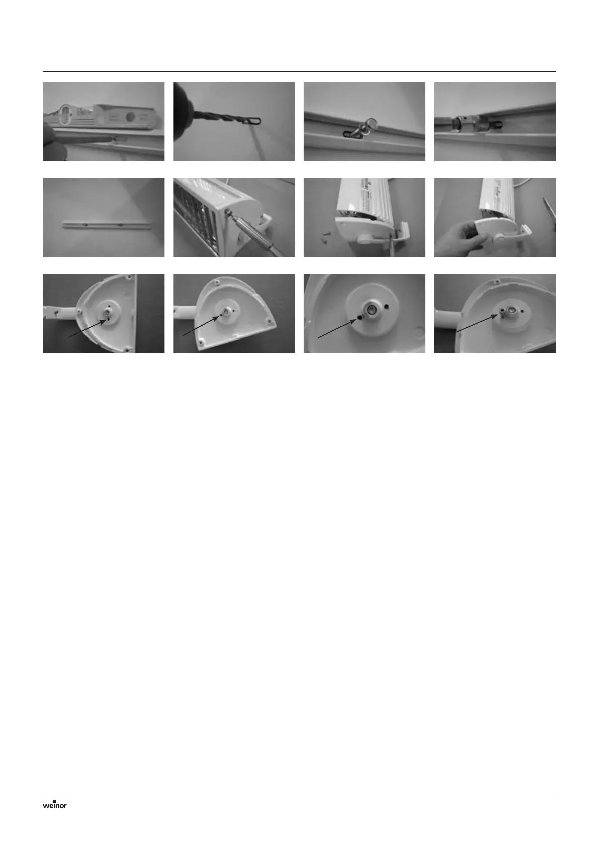
• Get the guiding section horizontal using a spirit level (Pict 4.2).
• Use the punchings in the section to mark the positions of the
holes.
• Drill suitable holes for mounting (Pict 4.3).
• Use the parts provided (or others suited to the location) to attach
the guiding section (Pict 4.4 – 4.6).
• Remove at least one of the headplates and use it to limit the
pivot angle so that it cannot point upwards. Place the Tempura
Universal on a suitable working surface to do this.
• Loosen the three countersunk self-tapping screw on the head-
plates (for this you need a Torx screwdriver T20, Pict 4.7 and 4.8).
• Remove the headplates (Pict 4.9)
• Turn the headplate to the lowest position it can be set to. Now
fit one of the supplied Allen screws (M4 x 8) into the lower
threaded hole (M4) until it touches (you need an Allen key SW3,
Pict 4.10 – 4.13).
• Attach the headplate to the housing again using the three
countersunk self-tapping screw.
• Push the Tempura Universal into the guiding section so that it
sits in the centre of the section. Check that the drain holes are at
the bottom.
• Use the grub screws to fix the Tempura Universal to the arms
(for this you need an Allen key SW3).
• Aligner le profilé de guidage horizontalement à l’aide d’un
niveau à bulle (Pict 4.2).
• Marquer la position des trous à l’aide des perforations dans les
profilés.
• Percer les trous d’installation appropriés (Pict 4.3).
• Fixer le profilé de guidage à l’aide des éléments de fixation
fournis (ou d’autres éléments adaptés aux conditions de construc-
tion) (Pict 4.4 à 4.6).
• Enlever au moins une plaque de recouvrement afin de limiter
l’angle de pivotement à ce niveau de sorte que le système de
chauffage ne puisse plus être orienté vers le haut. Pour cela,
placer le système Tempura Universal sur une plateforme de
travail.
• Desserrer respectivement les trois vis à tôle à tête conique au
niveau des plaques de recouvrement (un tournevis Torx T20 est
pour cela nécessaire, Pict 4.7 et 4.8).
• Retirer les plaques de recouvrement (Pict 4.9).
• Tourner la plaque de recouvrement jusqu’à la position de réglage
la plus basse. Visser à présent une vis à six pans creux fournie
(M4 x 8) dans le trou fileté inférieur (M4) jusqu’à ce qu’elle y
repose (une clé Allen de 3 est nécessaire, Pict 4.10 à 4.13).
• Fixer à nouveau la plaque de recouvrement à l’aide des vis à tôle à
tête conique au niveau du boîtier.
• Glisser le système de chauffage Tempura Universal dans le profilé
de guidage de sorte qu’il soit placé au milieu du profilé. Veiller
à ce que les trous d’écoulement de l’eau de pluie se trouvent sur
le côté inférieur.
• Fixer le système Tempura Universal à l’aide des tiges filetées dans
les bras (une clé Allen de 3 est pour cela nécessaire).
Pict 4.2 Pict 4.3 Pict 4.4 Pict 4.5
Pict 4.6 Pict 4.7 Pict 4.8 Pict 4.9
Pict 4.10 Pict 4.11 Pict 4.12 Pict 4.13
 Loading...