Do you have a question about the weintek MT6050iP and is the answer not in the manual?
Details environmental requirements for HMI installation, including NEMA rating.
Discusses electrical noise resistance and proper wiring for HMI operation.
Lists specific environmental factors like explosion hazards, gas resistance, and mounting.
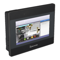
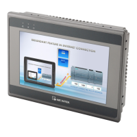
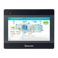
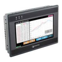
The MT6050iP and MT8050iP are Human Machine Interface (HMI) devices designed for industrial applications, providing a robust and reliable interface for controlling and monitoring machinery. These HMIs are rated NEMA 4, indicating a high level of protection against dust, dirt, and water, making them suitable for challenging industrial environments.
The primary function of these HMIs is to serve as a visual and interactive control panel for various industrial systems. They allow operators to monitor processes, input commands, and receive feedback from connected machinery. The devices are designed to conform to European CE requirements, ensuring they can resist electrical noise, although proper wire routing and grounding are crucial for optimal performance in severe cases.
The HMIs are equipped with a touch panel for user interaction, which requires calibration for accurate input. They support communication with controllers and other devices via multiple interfaces, including RS485, RS232, and Ethernet (for MT8050iP). This versatility allows them to integrate into a wide range of existing industrial networks.
The MT6050iP and MT8050iP are designed for vertical mounting on a flat surface enclosure. During installation, it's critical to secure the operator panel using all fastening holes and the provided brackets and screws to ensure stability. The installation environment should be free from severe mechanical vibration or shocks, and areas with explosion hazards due to flammable gases, vapors, or dusts must be avoided. Additionally, the units should not be operated in environments where acid gases, such as SO2, are present. They conform to UL508 machine safety standards for use in Pollution Degree 2 environments.
The HMIs are powered by a DC power supply within a voltage range of 24±20% Volts DC, compatible with most controller DC systems. It's essential to connect the positive DC line to the '+' terminal and the DC ground to the '-' terminal. To prevent potential damage to USB ports, the HMI should not be connected to a PLC and a PC simultaneously. When making connections, wires should be stripped about 3/8" of insulation, and the connector screws should be turned counterclockwise to open the gap, then clockwise to tighten after inserting the wire.
The devices utilize EasyBuilder 8000 software (V4.65.06 or later) for project development and configuration. This software allows users to create and download HMI projects. After powering up, the HMI displays an image, and users can access system settings by clicking a dedicated button (default password: 111111). For network connectivity, the MT8050iP can be connected via an RJ-45 cable, allowing users to configure network settings, including DHCP IP or a designated static IP address. The MT6050iP does not support RJ-45 connectivity.
The HMIs offer various communication options. COM1 supports RS485 (2-wire and 4-wire) and RS232. COM3 also supports RS485. For RS485/422 devices, cable lengths should be restricted to less than 500 feet (150m), and for RS232 devices, less than 50 feet (15m) to avoid communication problems. Shielded cables are recommended for long lengths or in electrically noisy environments. Cables should not be run next to AC power lines or sources of electrical noise.
To ensure safe operation, several precautions are highlighted. An internal fuse protects against incorrect DC power polarity and overcurrent conditions, though it's not guaranteed to prevent all damage. DC voltage sources should provide proper isolation from main AC power. A hard-wired EMERGENCY STOP should be integrated into any system using the HMI to comply with ICS Safety Recommendations. The HMI and inductive DC loads or input circuitry to the controller should not share the same power supply. Power wire length should be minimized (max 500m shielded, 300m unshielded), and twisted pair cables should be used for power and signal wires. Appropriate surge suppression devices are recommended if wiring is exposed to lightning or surges. AC, high energy, and rapidly switching DC power wiring should be separated from signal wires. A resistor and capacitor in parallel with the ungrounded DC power supply and frame ground can help dissipate static and high-frequency noise.
Upon delivery, users should unpack and check the unit for any damage. If damage is found, the supplier should be notified immediately. During installation, the operator panel should be placed on a stable surface to prevent damage from dropping or falling.
If the display does not come on within 5 seconds of power-up, power should be removed, and the wiring checked for proper connections before attempting to power up again. This indicates a potential issue with the power supply or internal fuse.
The product comes with a limited warranty against defects in design and manufacture. Defective products will be repaired or replaced at Weintek's discretion. The warranty period is 12 months from the manufacturing month. The warranty does not cover damage caused by Force Majeure, accidents, negligence, improper installation or misuse, repairs or disassembly by unauthorized technicians, or products with removed or damaged identification markings. This highlights the importance of proper installation, usage, and authorized servicing to maintain warranty coverage.
| Display Type | TFT LCD |
|---|---|
| Power Input | 24 V DC |
| Enclosure | Plastic |
| Touch Panel | Resistive |
| CPU | 32-bit RISC |
| Memory | 128 MB Flash |
| Serial Ports | 2 |
| USB | 1 x USB Host |
| Operating Temperature | 0°C |
| Storage Temperature | -20 to 60 °C |
| Protection Class | IP65 |