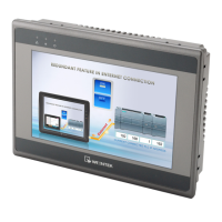
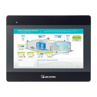
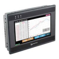
Installation and Startup Guide
This document covers the installation of MT6051/8051iP Series HMI, for the detailed specifications and
operation, please refer to Brochure and EasyBuilder Pro User Manual.
Install Environment:
MT6051/8051iP Series HMI is NEMA 4 rated (Indoor Only).
MT6051/8051iP Series has been tested to conform to European CE
requirements. This means that the circuitry is designed to resist the effects of
electrical noise. This does not guarantee noise immunity in severe cases. Proper
wire routing and grounding will insure proper operation.
Environmental
Considerations
(1) Make sure that the displays are installed correctly and that the operating
limits are followed. Avoid installing units in environments where severe
mechanical vibration or shocks are present.
(2) Do not operate the unit in areas subject to explosion hazards due to
flammable gases, vapors or dusts.
(3) Do not install the unit where acid gas, such as SO2 exists.
(4) This device should be mounted in the vertical position and for use on the flat
surface enclosure.
(5) Conform to UL508 (ISBN 0-7629-0404-6) machine safety for use in
Pollution Degree 2 Environment.
(6) Relative Humidity: 10% ~ 90% (non-condensing)
Unpacking the Unit
Unpack and check the delivery. If damage is found, notify the supplier.
NOTE: Place the operator panel on a stable surface during installation. Dropping it or letting it fall
may cause damage.
(1) Installation Instruction, 2-sided A4 *1
(2) Human Machine Interface *1
(3) Power Connector *1
(4) Brackets & Screws *1 pack
Installation Instructions
Secure the operator panel in position, using all
the fastening holes and the provided brackets
and screws. Screw Torque: 2.6 ~ 3.9 lbf.in.
(For reaching waterproof effect and preventing
the panel from being deformed.) Panel Cutout:
119 mm x 93 mm
Power Connections
NOTE:
1. Connect positive DC line to the ‘+’ terminal and
the DC ground to the ‘-’ terminal.
2. When downloading project using a USB cable,
do not connect HMI with PLC and PC
simultaneously, for electric potential difference
may result in damage to HMI or PC.
System Settings
When HMI is powered up and displays image,
click the system setting button.
(Default System Password: 111111)
It is necessary to connect the HMI to
your network through a RJ-45 cable.
(N/A for MT6051iP)
EasyBuilder Pro Software Settings
Launch EasyBuilder Pro software, select your project file, press F7 shortcut key to open the download
dialog box:
For MT6051iP, select USB cable /
For MT8051iP, select Ethernet > IP tab > Enter your HMI IP > Click Download to download this project file
to HMI.
Using screensaver and backlight saver is recommended in order to avoid image persistence caused by
displaying the same image on HMI for a long time.
(Please refer to EasyBuilder Pro User Manual for software operation details.)
MT6051iP MT8051iP series
Installation Instruction
Go to the Network tab, you may choose
to auto get DHCP IP, or designate your
own IP.