EasyManua.ls Logo

Weiser Obsidian User Manual

Weiser Obsidian
4 pages
To Next Page IconTo Next Page
Page #1 background imageLoading...
Page #1 background image
Required tools
Ruler
Hammer Wood block
Phillips head screwdriver
Additional Tools (depending on application)
A
K or L
(2x)
A
A
B
B
B
A
B
If drilling a new door, use the supplied template and the complete
door drilling instructions available at www.weiserlock.com/doorprep.
Note: Additional door preparation may be
required for doors with 11/2" (38 mm) holes.
Consult the deadbolt drilling instructions at
www.weiserlock.com/doorprep.
or
backset
Measure to conirm that the hole in
the door is either 21/8" (54 mm) or
11/2" (38 mm).
Measure to conirm that the backset is
either 23/8" or 23/4" (60 or 70 mm).
23/8" or 23/4"
60 or 70 mm
13/8" –2"
35 – 51 mm
Measure to conirm that the hole in
the door edge is 1" (25 mm).
Measure to conirm that the door is
between 13/8" and 2" (35 mm and
51 mm) thick.
A
A B
C
D
B C D
Is the door edge chiseled?
Is the D-shaped hole centered in the door hole?
Which latch are you installing?Hold the latch in front of the door hole, with the latch
face lush against the door edge.
21/8"
54 mm
11/2"
38 mm
1"
25 mm
YES
YES
NO
NO
Use latch “A”. If the
latch bolt is not already
extended, extend the
latch bolt as shown.
No adjustment is required.
Proceed to next step.
D-shaped hole D-shaped hole
Rotate latch face as
shown to extend latch.
wood
block
Use latch “B”. If the
latch bolt is not already
extended, extend the
latch bolt as shown.
Latch “A Latch “B”
or
chiseled
not
chiseled
or
1
Prepare the door and check dimensions
2
Install the latch and strike
or
Parts in the box
Latches
Strike
C
A
B
Exterior Touchscreen
Adapter
Ring
D
Mounting
Plate
Fasteners
03809
K
L
64109
U
49191
T
Interior Assembly
G
F
H J
E
(1-3/8" • 35 mm)
(2" • 51 mm)
64843
64845
Q
S
(1-3/4" • 44 mm)
64844
R
Batteries
V
SL03031011
M
N
P
C
Longer screws
install closest to
the door jamb.
door frame
E
Install strike on the door frame.
Make sure the hole in the door frame is drilled a
minimum of 1" (25 mm) deep.
P (2x)
M or N (2x)
actual
size
K L M N
P
1 / 4
ENGLISH
66460001
Rev 02
GED2350
ZWave® Plus
Installation and User Guide
Weiser
Technical Support
1-800-501-9471
www.weiserlock.com
Question and Answer IconNeed help?

Do you have a question about the Weiser Obsidian and is the answer not in the manual?

Weiser Obsidian Specifications

General IconGeneral
Keyless EntryYes
Power4 AA Batteries
Power SourceBattery
Weather ResistanceYes
Battery Life1 year
SecurityANSI Grade 2
Lock TypeDeadbolt
Backup Power9V battery
Auto-LockYes
Door Thickness1.375 to 2.25 inches

Summary

Prepare Door and Check Dimensions

Check Door Hole Diameter

Confirm the primary hole diameter in the door is 2-1/8" or 1-1/2".

Verify Backset Measurement

Measure the backset to ensure it is 2-3/8" or 2-3/4".

Measure Door Edge Hole

Confirm the hole in the door edge measures 1" (25 mm) for the latch.

Confirm Door Thickness

Ensure the door thickness is between 1-3/8" and 2" (35-51 mm).

Install Latch and Strike

Select Latch Based on Door Edge

Choose latch 'A' if the door edge is chiseled, or latch 'B' if not.

Install Latch and Check Centering

Position latch with face flush, and verify D-shaped hole centering.

Install Door Frame Strike

Mount the strike on the door frame, ensuring a minimum 1" deep hole.

Install Exterior Touchscreen

Verify Door Hole Diameter

Confirm door hole diameter (2-1/8" or 1-1/2") for component selection.

Select Mounting Screws

Choose appropriate screws (Q, R, or S) based on door thickness (1-3/8" to 2").

Mount Exterior Assembly

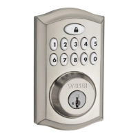
Install the exterior touchscreen and mounting plate, routing cable properly.

Install Interior Assembly

Prepare Interior Assembly

Remove battery cover and ensure turnpiece is vertical before mounting.

Mount Interior Assembly

Attach interior assembly to mounting plate, securing cable connection.

Install Batteries and Perform Door Handing

Install Batteries

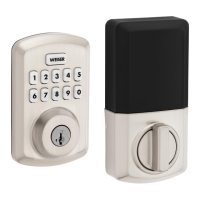
Insert 4 AA batteries into the battery pack with correct polarity.

Initiate Door Handing Process

Insert battery pack with door open; lock learns orientation automatically.

Verify Door Handing Success

Check for a flashing checkmark (success) or 'X' pattern (failure).

Add Lock to Smart Home System

Initiate Pairing Process

Start adding the lock via your smart home controller instructions.

Enter Add Mode on Lock

Press button 'A' on the interior to enter Add Mode.

Troubleshoot Connection Issues

Follow steps to remove and re-add if the lock fails to connect.

Add User Codes

Access Programming Mode

Press Program button on interior, then checkmark symbol.

Enter and Confirm Codes

Input user code (4-8 digits) and press lock symbol to program.

Interpret Programming Results

Check for success (checkmark, one beep) or failure ('X', three beeps).

Test Lock Operation

Activate the Screen

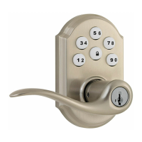
Touch the screen with palm, hand, or fingers until digits illuminate.

Lock and Unlock Door

Use programmed codes to unlock; press Lock symbol to lock.

SecureScreen Feature

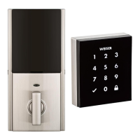
Understand SecureScreen's random digits for enhanced security.

Install Interior Cover

Cover Installation

Install the interior cover, aligning the turnpiece and securing with screws.

System Alerts and Troubleshooting

Common System Alerts

Understand display alerts like 'X' pattern, checkmark, and lock symbols.

Manual Door Handing Procedure

Manually initiate the door handing process by holding the Program button.

Low Battery Power

Use a 9-Volt battery to temporarily power the touchscreen when batteries are low.

Important Safeguards and Network Info

Safety Precautions

Follow instructions, remind family, protect codes, and dispose of batteries properly.

Remove Lock from Network

Follow smart home system instructions to remove the lock from the network.

Z-Wave System Notes

Understand Z-Wave Plus requirements and interoperability for this product.

Related product manuals