Do you have a question about the Welch Allyn CSM 7500 and is the answer not in the manual?
Instructions and procedures for operating the CSM device.
Information related to maintenance and repair of the CSM.
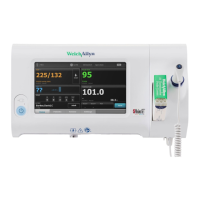
Description of the primary touchscreen display interface.
The device performs a POST upon initial startup.
How the CSM displays error messages upon POST failure.
Details displayed in the top status bar (clinician, time, battery).
Description of parameter panes and their interactive functions.
How to navigate between different screens using the primary controls.
Visual representation of remaining battery capacity and time.
Amber and red alerts for low battery conditions.
Distinction between physiological and technical alarms.
Details on alarm priority levels, background colors, and tones.
Information on firmware, configuration, hardware, and connectivity.
Procedure for logging into the advanced settings menu.
Configuration options for NIBP units, algorithm, and target pressure.
Specifying ESSID, radio band, and network alarms.
Configuring wireless security protocols and encryption.
Setting device information and performing touchscreen calibration.
Loading or saving device configuration files.
Procedure for saving system logs to a USB drive.
Resetting the device to defaults and upgrading firmware.
Annual functional verification for the NIBP module.
Annual functional verification for the SpO2 module.
Annual functional verification for the SureTemp Plus module.
Annual functional verification for the Braun thermometer.
Recommended battery replacement after 2 years of use.
Definition of symptoms as unexpected behavior not triggering alarms.
Procedure for saving the log file to a USB drive.
Need to replace internal parts like boards and cables.
Instructions for disassembly and reassembly are provided.
A full functional verification is required after service.
Individual parts like boards and pumps are replaced, not repaired.
Service kits include parts typically replaced together.
Importance of using Electrostatic Discharge (ESD) protection.
Always remove mains and battery first before opening the device.
Ensuring all cables are inserted correctly and locked where applicable.
Using a torque driver to prevent damage to the housing during reassembly.
Table detailing torque specifications for various screws.
Calibration functions are locked and require a license to unlock.
Review device info, schedule maintenance, install updates, view logs, user admin.
Performing NIBP accuracy, leak, and over-pressure tests.
Programming device SN after main PCB exchange (Gold license only).
Performing complete functional verification and calibration (Gold license only).
Using WAST to program the device serial number and model number.
Steps required to re-initialize the NIBP module after replacement.
Updating the device firmware to the latest available version.
Conducting a full functional calibration using WAST and a gold license.
Steps to access device settings within the WAST application.
Procedure: Go to Configure -> Current settings -> change.
Inputting device SN, host controller SN, and model number, then saving.
Navigating to the firmware upgrade section within WAST.
Initiating a check for available upgrades (requires internet connection).
Selecting the device and initiating the upgrade process.
Navigating to the verify and calibrate functions within WAST.
Selecting the NIBP sensor and starting the process.
Confirming the initialization of the NIBP board.
Following on-screen instructions for calibration tests (Power, Pressure).
Performing basic verification as periodic maintenance using WAST Standard.
Performing comprehensive verification using WAST Gold license.
When to perform full verification: drop, doubt, opening, part replacement.
Steps within WAST to perform device verification and calibration.
Selecting 'Perform All' for comprehensive device checks.
Executing all tests and calibrations by following on-screen prompts.
Users can create configurations online for deployment to devices.
Creating, editing, and downloading existing configuration files.
Process for creating new configuration files for the CSM.
| Category | Medical Equipment |
|---|---|
| Manufacturer | Welch Allyn |
| Model | CSM 7500 |
| NIBP Technology | Oscillometric |
| Display | Color LCD |
| Battery | Rechargeable Lithium-ion |
| Data Storage | Internal Memory |
| Connectivity | USB, Ethernet |
| Blood Pressure Monitoring | Yes |
| Pulse Oximetry | Yes |
| Treadmill Integration | Yes |
| Bicycle Ergometer Integration | Yes |
| Parameters | NIBP, SpO2 |
| Power Source | AC Power, Battery |
| Weight | Approximately 8 lbs (3.6 kg) |