Do you have a question about the Welch Allyn SureTemp 679 and is the answer not in the manual?
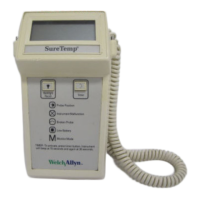
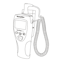
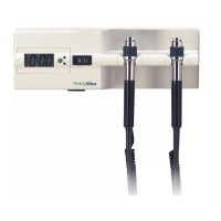
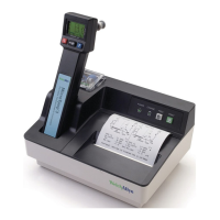
Describes the main components of the thermometer system.
Details the type of batteries used and their life.
Describes the main instrument's similarity to previous models.
Explains the wall holder and its features.
Discusses probe compatibility and types.
Mentions probe cover compatibility.
Explains instrument reset and power-up self tests.
Describes the display test sequence during power-up.
Details self-tests for the probe warmer circuit.
Provides expected battery life and factors affecting it.
Explains the primary mode for temperature taking.
Describes the mode for long-term temperature monitoring.
Details the pulse timer function for Model 678.
Explains the display backlight feature for Model 678.
How to switch between Fahrenheit and Celsius scales.
How to recall the last measured temperature.
Describes how to enter and use the Biotech mode.
How to check the instrument's software version.
Setting the default temperature-taking algorithm.
Displays current battery voltage and low battery indicators.
Counts predictive temperature actuations for calibration.
Configures the anti-theft timeout based on temperature count.
Describes the anti-theft audio alarm feature.
How to access and view stored error messages for Model 679.
Instructions for regular cleaning of the instrument and probe.
Procedure for sterilizing the thermometer using ETO gas.
Step-by-step guide for replacing batteries.
Steps for performing a basic calibration test using a key.
Procedure for calibration using the Model 9600 tester.
Provides a high-level summary of the instrument's ICs.
Details features like probe type detection and warming.
Explains the function of the probe presence switch.
Describes the technical operation of Normal Mode.
Explains the battery pack and voltage range.
Describes the circuit for detecting low battery status.
Identifies the microcontroller and its core functions.
Explains the microprocessor reset and self-test sequence.
Details the clock generation circuit.
Explains how temperature is measured and shown.
Describes the A/D converter's role in measurement.
Explains the single slope converter and ratio calibration.
Details the capacitor discharge and comparator logic.
How the instrument identifies connected probes.
Explains probe identification logic and connector signals.
Describes the probe warming feedback control system.
Details the probe warmer circuitry components and function.
Describes the LCD and backlight components.
Explains the LCD structure and connection.
Details the LED backlight operation and control.
Explains the probe switch operation and override.
Describes the function and input of the mode button.
Explains the timer button function for Model 678.
Describes the serial port for testing and integration.
Explains when the horn is activated and its types of beeps.
Classifies error codes: Probe, Ambient Temp, Dead Battery, Instrument.
Lists instrument circuitry error codes and their self-test descriptions.
Lists tools and equipment needed for troubleshooting.
Lists symptoms, causes, and procedures for common issues.
Continues troubleshooting symptoms, causes, and procedures.
Continues troubleshooting symptoms, causes, and procedures.
Continues troubleshooting symptoms, causes, and procedures.
Continues troubleshooting symptoms, causes, and procedures.
Discusses repairs that can be done in the field.
Lists parts available for field service.
Lists part numbers for Model 678/679 replacement parts.
Lists replacement parts for circuit board assemblies.
Provides instructions for disassembling the thermometer.
Continues disassembly instructions, covering the electronics assembly.
Illustrates the assembly breakdown of the thermometer.
Shows the component and solder sides of the main PCB.
Illustrates the assembly of electronic components.
| Brand | Welch Allyn |
|---|---|
| Model | SureTemp 679 |
| Category | Thermometer |
| Language | English |