EasyManua.ls Logo

Wellsys WS 12000 - User Manual

Wellsys WS 12000
4 pages
Print Icon
To Next Page IconTo Next Page
Loading...
Step 1: Remove all 9 screws circled
above. Then remove the top & rear
panel.
Step 2: Remove the two screws
indicated above and remove the
front panel.
Step 3: Peel back insulation to
expose the 'ice making' sensor and
the 'ice full' sensor receive.
Step 4: Remove
everything from the upper front half
of the holding tank.
Step 5: Remove
the two screws located on the
holding tank, just behind the panel.
---------------------------------------
Phillips head screw driver
TDS meter
Microfiber towels & paper towels
Gloves
5 gallon bucket
Thermometer
Tubing & tube cutters
Pledge multi-surface
Hydrogen Peroxide
You will need:
WS
12000
Annual
PM
Guide
The WS 12000 Unit needs preventative maintenance every year.
Follow the instructions below for appropriate instructions.
Step 6: Carefully
remove the Styrofoam bin lid.
Part 1: Sanitizing the Unit
Pre-Sediment Filter (ICESEO): 1 year or 2500 gallons max
Pre-Carbon Filter (ICEPREC): 1 year or 2500 gallons max
Reverse Osmosis (ICERO): 3 years or 4500 gallons max
TCR Filter (ICEPOSTCA): 3 years or 2500 gallons max
Filter Change Regime:
What to do:
Question and Answer IconNeed help?

Do you have a question about the Wellsys WS 12000 and is the answer not in the manual?

Summary

Part 1: Sanitizing the Unit

Remove Top and Rear Panel

Remove the top and rear panel by unscrewing all nine circled screws.

Remove Front Panel

Remove the front panel by unscrewing the two indicated screws.

Expose Ice Sensors

Peel back insulation to expose the 'ice making' sensor and 'ice full' sensor receive.

Clear Holding Tank Contents

Remove everything from the upper front half of the holding tank.

Remove Holding Tank Screws

Remove two screws located on the holding tank, just behind the panel.

Remove Styrofoam Bin Lid

Carefully remove the Styrofoam bin lid.

Remove Ice Tray Screws

Remove the screws securing the ice tray assembly.

Remove Ice Tray

Slide the ice tray out of the unit.

Remove Grid Screws and Grid

Remove screws and then remove the grid from the unit.

Remove Evaporator Screws

Remove screws to access the evaporator.

Remove Evaporator

Gently lift and remove the evaporator for easier cleaning.

Remove Ice Tray Liner Screws

Remove screws to detach the ice tray liner, noting hidden ones.

Remove Ice Bin Liner

Remove plastic plugs and pull the ice bin liner out of the unit.

Clean Removed Parts

Liberally spray removed parts with hydrogen peroxide solution and rinse.

Access Ambient Tank

Slide clips and remove screws to gain access inside the ambient tank.

Clean Ambient Tank

Liberally spray the inside of the ambient tank and rinse in a sink.

Part 2: Filter Replacement

Remove Sediment Filter

With water off, turn and remove the Sediment filter.

Prepare for Flushing

Remove tube, insert new tubing into manifold and bucket for flushing.

Install and Flush Pre-Carbon Filter

Insert new Pre-Carbon filter, turn on water, and flush for 5 minutes.

Relocate Filters and Flush Post-Carbon

Relocate Pre-Carbon filter, install Post-Carbon, and repeat flushing procedure.

Finalize Filter Placement and Check

Place carbon filters correctly, reconnect tube, and verify water production.

Overview

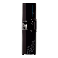
The WS 12000 Unit is a water purification and ice-making appliance designed for regular use, requiring annual preventative maintenance to ensure optimal performance and hygiene. This guide outlines the necessary steps for both sanitizing the unit and replacing its filters, ensuring the continued delivery of clean water and ice.

Function Description

The WS 12000 Unit serves as a comprehensive water treatment system, incorporating multiple filtration stages to purify incoming water and an integrated ice maker to produce ice. The filtration system is designed to remove various impurities, sediments, and contaminants, providing users with high-quality drinking water. The ice-making function is automated, with sensors to detect ice levels and ensure a continuous supply. The unit includes a hot tank for heated water, indicating its capability to provide water at different temperatures.

Usage Features

The unit is designed for user convenience, with a multi-stage filtration system that includes a Pre-Sediment Filter, Pre-Carbon Filter, Reverse Osmosis (RO) membrane, and a Post-Carbon Filter. Depending on the model, it may also include an Ultra Fine filter, BIO-Sure+ filter, and a TCR Filter. These filters work in sequence to progressively refine the water. The ice-making process is managed by an "ice making" sensor and an "ice full" sensor, which regulate production to prevent overfilling and ensure a consistent supply. The unit features a drain mode switch and a hot tank switch, allowing users to manage specific functions as needed. The design incorporates easily removable panels and components for maintenance, such as the top and rear panels, front panel, ice tray, grid, evaporator, and ice bin liner.

Maintenance Features

Preventative maintenance for the WS 12000 Unit is recommended annually and is divided into two main parts: sanitizing the unit and replacing filters.

Sanitization Process:

The sanitization process involves a thorough cleaning of all water and ice contact surfaces to prevent bacterial growth and maintain hygiene. This requires a Phillips head screwdriver, TDS meter, microfiber towels, paper towels, gloves, a 5-gallon bucket, a thermometer, tubing and tube cutters, Pledge multi-surface cleaner, and hydrogen peroxide.

  1. Disassembly: The process begins by removing the top, rear, and front panels by unscrewing them. This exposes internal components.
  2. Sensor Access: Insulation is peeled back to expose the "ice making" sensor and the "ice full" sensor receiver, which are critical for ice production.
  3. Holding Tank Preparation: All contents from the upper front half of the holding tank are removed. Two screws on the holding tank, behind the panel, are removed, followed by the careful removal of the Styrofoam bin lid.
  4. Ice System Component Removal: Screws holding the ice tray are removed, allowing it to be slid out. The grid is then removed from the unit. Additional screws are removed to facilitate the removal of the ice bin liner. The evaporator is gently lifted and moved aside for easier cleaning. Screws securing the ice tray liner are removed, with two hidden screws requiring a stubby-nose screwdriver. Plastic plugs are removed, and the ice bin liner is pulled out.
  5. Cleaning Solution Preparation: A sanitizing solution is prepared by mixing 1 part hydrogen peroxide with 5 parts water and placed in a spray bottle.
  6. Cleaning Application: All ice-making and storage surfaces are liberally sprayed with the solution and wiped clean with a soft rag. It is crucial to avoid using anything abrasive on these surfaces to prevent damage.
  7. Component Rinsing: The removed parts are liberally sprayed with the solution and rinsed in a sink.
  8. Ambient Tank Access and Cleaning: Clips on the ambient tank are slid into an open position, and four screws in the top corners are removed to gain access inside. The interior of the ambient tank is then liberally sprayed with the solution and rinsed in a sink.

Filter Replacement Process:

Filter replacement is a critical part of annual maintenance to ensure continued water quality. This process requires the same tools as sanitization, plus new filters. The filter change regime specifies replacement intervals based on time or gallons used:

  • Pre-Sediment Filter (ICESEO): 1 year or 2500 gallons max
  • Pre-Carbon Filter (ICEPREC): 1 year or 2500 gallons max
  • Reverse Osmosis (ICERO): 3 years or 4500 gallons max
  • TCR Filter (ICEPOSTCA): 3 years or 2500 gallons max
  • Ultra Fine: 3 years or 4500 gallons max (if applicable)
  • BIO-Sure+: 1 year or 750 gallons max (if applicable)
  1. Water Supply Shut-off: The water supply to the unit is turned off.
  2. Sediment Filter Removal: The Sediment filter is removed by turning it to the left. It's important to ensure the O-ring remains with the filter and not on the filter head.
  3. Manifold Preparation for Flushing: A tube is removed from the manifold, and a 1-2 foot length of 1/4" tubing is inserted into the manifold, leading to a bucket for flushing.
  4. Pre-Carbon Filter Installation and Flushing: The new Pre-Carbon filter is inserted into the sediment filter location. The water supply is turned on, and the filter is flushed for 5 minutes.
  5. Filter Relocation: Once the Pre-Carbon filter is flushed, it is removed from the sediment filter location and installed in its designated Pre-Carbon location. This process is repeated for the Post-Carbon filter.
  6. Final Filter Placement and System Check: After flushing, the carbon filters are relocated to their appropriate positions, and the original tube is reinserted into the manifold. A crucial note is to ensure the unit is making water before reassembling, as a leak detector issue is a common reason for the unit not to fill after PM.

For additional assistance, users can contact Wellsys Tech support directly.

Wellsys WS 12000 Specifications

General IconGeneral
Power Consumption (Heating)500W
Power Consumption (Cooling)100W
Water TemperaturesHot, Cold
Cooling SystemCompressor
Frequency60Hz
Hot Water Temperature90°C

Related product manuals