1
/
4
-DIN,
1
/
8
-DIN &
1
/
16
- DIN Controllers & Indicators - Product Manual
59305, Issue 5 – March 2005 P6700, P8700& P4700 Model Group Page 51
P6100, P8100 & P4100 Controllers – Serial Communications Parameters
The Modbus parameter addresses, and the possible ASCII message types and parameter
indents for the P6100, P8100 & P4100 are detailed below. RO indicates a parameter is read
only, R/W indicates it can also be written to. Communications writes will not implemented if
the Communications Write Parameter is disabled. Refer to the Modbus and ASCII
Communications sections of this manual for details of the protocols used.
Bit Parameters
Bit parameters are not applicable to the ASCII protocol.
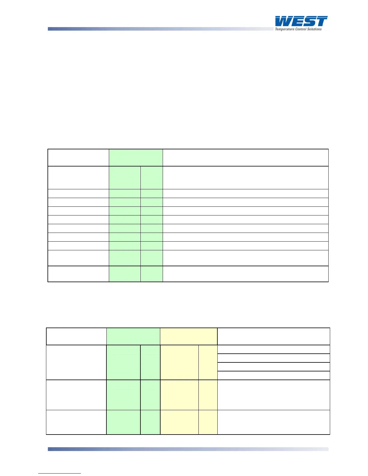
Table 14. P6100, P8100 & P4100 Communications - Bit Parameters
Parameter Modbus
Parameter No.
Notes
Communication
Write Status
1
RO 1 = Write Enabled, 0 = Write Disabled. A negative
acknowledgement (exception code 3) is sent to write
commands if communications writes are disabled
Auto / Manual
2
R/W 1 = Manual Control, 0 = Automatic Control
Self Tune
3
R/W 1 = Activate(d), 0 = Dis-engage(d)
Pre tune
4
R/W 1 = Activate(d), 0 = Dis-engage(d)
Alarm 1 Status
5
RO 1 = Active, 0 = Inactive
Alarm 2 Status
6
RO 1 = Active, 0 = Inactive
Setpoint Ramping
7
R/W 1 = Enable(d), 0 = Disable(d)
Loop Alarm Status
10
R/W 1 = Active/Enable, 0 = Inactive/Disable
Loop Alarm
12
R/W Read to get loop alarm status. Write 0/1 to
disable/enable.
Digital Input 2
13
RO State of Option B digital input.
(RSP models only).
To set the bit value to 1 write FF, to set the bit value to 0 write 00. Refer to Function Code 05 in the
Modbus Communications section.
Word Parameters
Table 15. P6100, P8100 & P4100 Communications - Word Parameters
Parameter Modbus
Parameter No.
ASCII Ident &
Message Types
Notes
Current value of PV.
If under-range = 62976 (<??>5 ASCII)
If over-range = 63232 (<??>0 ASCII)
Process Variable
1
RO
M
Type 2
RO
If Sensor break = 63488 (ASCII = n/a)
Setpoint
2
R/W
S
Type 2
Type 3/4
RO
R/W
Value of currently selected setpoint.
(Target setpoint if ramping).
Parameter is read only if the current
setpoint is RSP.
Output Power
3
R/W
W
Type 2
Type 3/4
RO
R/W
0% to 100% for single output; −100%
to +100% for dual output control.
Read Only if not in manual control.