1
/
4
-DIN,
1
/
8
-DIN &
1
/
16
- DIN Controllers & Indicators - Product Manual
59305, Issue 5 – March 2005 P6700, P8700& P4700 Model Group Page 63
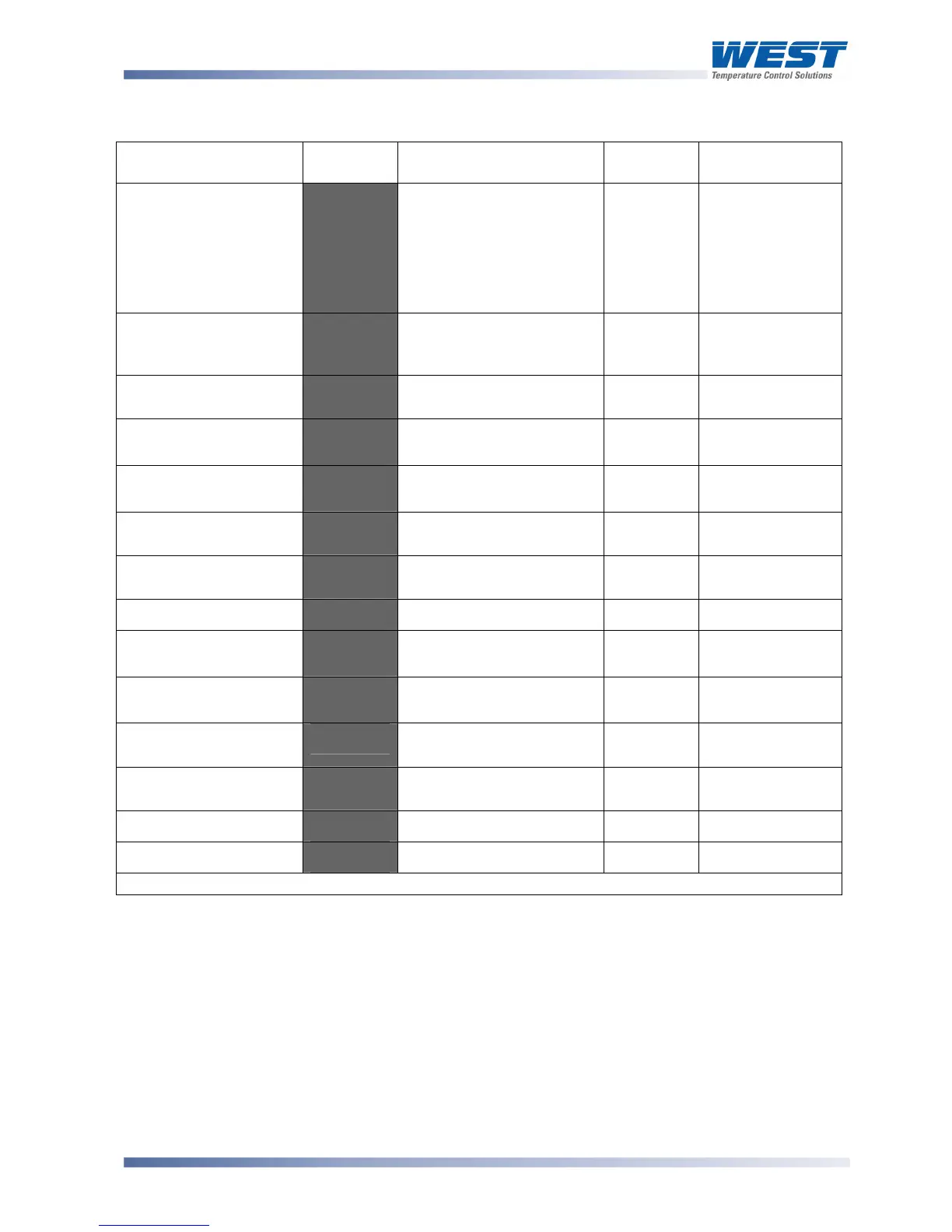
Table 17. P6700, P8700 & P4700 Set Up Mode Parameters
Parameter Lower
Display
Upper Display
Adjustment Range
Default
Value
When
Visible
Limit Setpoint value
:-'
Scaled Range Minimum to
Scaled Range Maximum
Range
max when
$#9+=)<
Range min
when
$#9+=+"
Always
Limit Hysteresis
)C:#'
1 LSD to full span in
display units, on the safe
side of the limit SP
2'
Always
Input Filter Time
constant
&<+#'
OFF, 0.5 to 100.0 secs in
0.5 sec increments
3. @'
Always
Process High Alarm 1
value*
-N52'
Range Min. to Range
Max.
Range
Max.
5+52 = -B)<'
Process Low Alarm 1
value*
-+52'
Range Min. to Range
Max.
Range
Min.
5+52 = -B+"'
Deviation Alarm 1
Value*
D5+2'
±span from setpoint
G'
5+52
= D.'
Band Alarm 1 value*
65+2'
1 LSD to full span from
setpoint.
G'
5+52
= 65%D'
Alarm 1 Hysteresis*
5)M2'
Up to 100% of span
2'
Always
Process High Alarm 2
value*
-N53'
Range Min. to Range
Max.
Range
Max.
5+53 = -B)<'
Process Low Alarm 2
value*
-+53'
Range Min. to Range
Max.
Range
Min.
5+53 = -B+"'
Deviation Alarm 2
Value
D5+3'
±span from setpoint
G'
5+53 = D.'
Band Alarm 2 value*
65+3'
1 LSD to full span from
setpoint.
G'
5+53
= 65%D'
Alarm 2 Hysteresis*
5)M3'
Up to 100% of span
2'
Always
Set-up Lock Code
:+"?'
0 to 9999
2@'
Always
**First Operator mode displays follows.
Note:
Alarm parameters marked * are repeated in Configuration Mode.
Note:
**Once the complete list of Set Up Mode parameters has been displayed, the first
Operator Mode display is shown without exiting from Set Up Mode.
CAUTION:
An excessively large filter time could significantly delay detection of a limit
condition. Set this value to the minimum required to remove noise from the process
variable.