1
/
4
-DIN,
1
/
8
-DIN &
1
/
16
- DIN Controllers & Indicators - Product Manual
Page 68 P6700, P8700& P4700 Model Group 59305, Issue 5 – March 2005
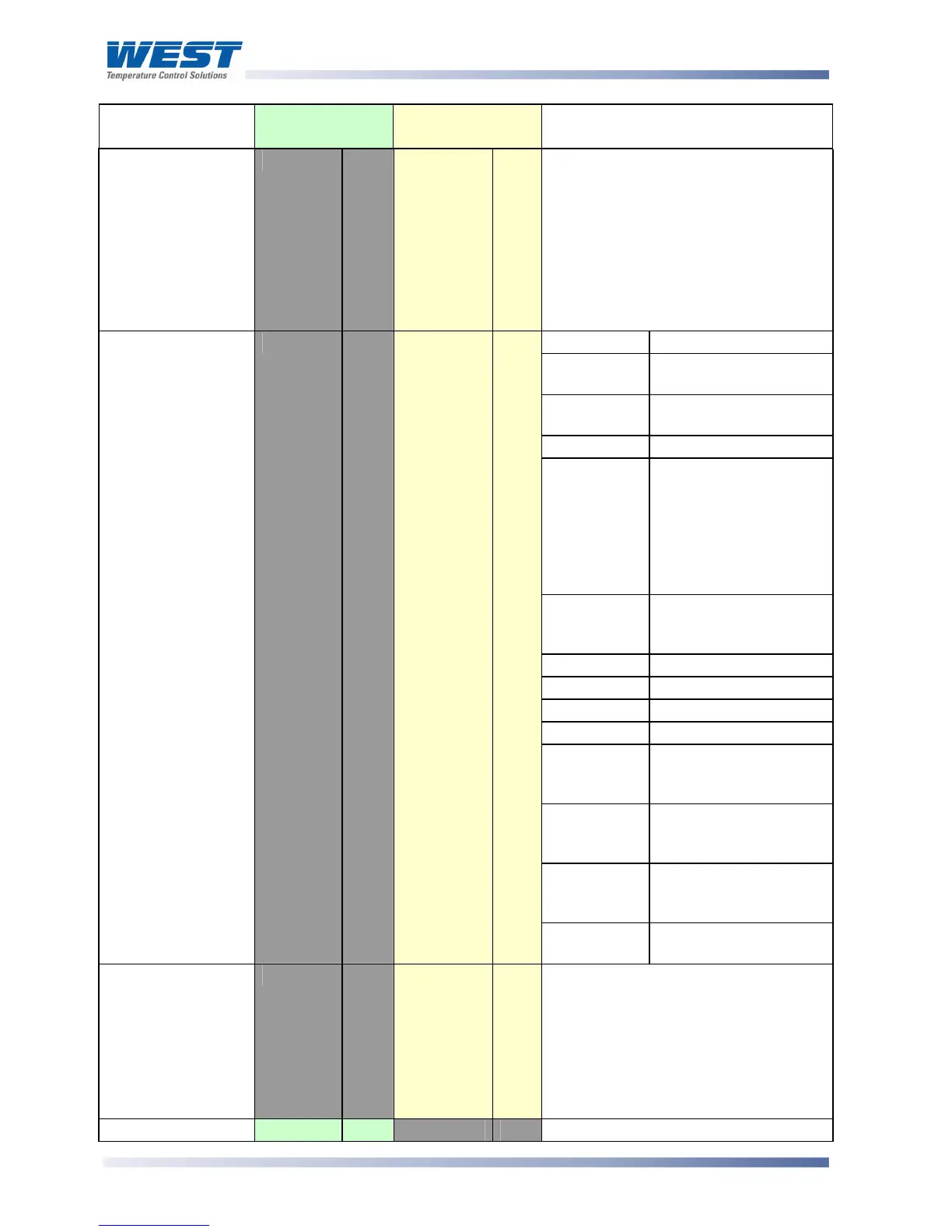
Parameter Modbus
Parameter No.
ASCII Ident &
Message Types
Notes
Controller
Commands
Z
Type 3/4
R/W
The Type 3 {DATA} field must be one
of three five-digit numbers:
00150 = Reset Limit Outputs
00160 = Reset Hold Value
00170 = Reset Exceed Time value
The response contains the same
{DATA}. A negative acknowledgement
will be returned if Reset in not
possible or already implemented.
Bits Meaning
0 Alarm 1 status:
0 = Activated, 1 = Safe
1 Alarm 2 status:
0 = Activated, 1 = Safe
2 Not used
3 Change Indicator:
0 = No changes, since
Controller Status was
last read.
1 = A parameter other
than Controller Status
or PV has changed
4 Comms write status:
0 = Disabled
1 = Enabled
5 Not used
6 Not used
7 Not used
8 Not used
9 Limit status:
0 = Not Exceeded, 1 =
Exceeded
10 Limit Relay Status:
0 = safe, 1 = Latched
Off
11 Limit Action:
0 = Low Limit, 1 = High
Limit
Controller Status
L
Type 2
RO
12 Annunciator status:
0 = inactive, 1 = Active
Scan Table
]
Type 2
RO
Reads back main process values.
Response is: L{N}25aaaaabbbbb
cccccdddddeeeeeA* where:
aaaaa = Limit Setpoint value
bbbbb = Process Variable value
ccccc = Hold value
ddddd = Exceeded Time value
eeeee = Controller Status (see above)
Equipment ID
122
RO
The four digit model number 6700