THE ENGINE
A
The oil pump is
of
the eccentric rotor, non-draining
type and is driven from the camshaft.
A full-flow oil filter
is
mounted
on
the side
of
the
crankcase
The fuel injection pump
is
of
the C.A.V. distributor
type incorporating an automatic advance device and a
governor, both
of
which are hydraulically operated. The
pump
is
flange-mounted
on
the right-hand side
of
the
engine
and
is
driven 'by the camshaft through a shaft and
gear mounted transversely in the crankcase.
The fuel lift pump
is
of
the A.C. mechanical type and
is
driven by the engine camshaft. Fuel oil
is
delivered to
the injection pump via
an
external filter
of
the C.A.V.
bowl-less type, having a renewable paper element.
C.A.
V.
Pintaux-type fuel injection nozzles are used.
and a leak-off pipe returns any back-leakage
of
fuel from
the injector nozzles to the supply side
of
the fuel system.
The leak-off pipe is connected to the main fuel filter to
provide continuous air-venting
of
the filter
and
to prevent
the build-up
of
excessive pressure inside the filter.
A centrifugal fresh water pump mounted on the front of
the cylinder block and the
raw
water pump mounted below
the combmatlon manIfolds and expansion tank,
along
with
the alternator
are
belt
driven
from the crankshaft pully.
The cooling system
is
controlled by a thermostat
in
the
cylinder head.
Section A.3
LUBRICATION SYSTEM
The oil supply
is
carried in the sump below the
cylinder block
and
the filler cap is fitted
on
the valve
rocker cover. The oil level indicator rod
is
on
the right-
hand side
of
the engine
and
is marked
to
indicate both
the maximum
and
minimum
le~els.
An eccentric-rotor, non-draining-type oil pump,
located
in
the left-hand side
of
the crankcase, is driven
from the camshaft. Oil
is
drawn through a gauze strainer
mounted inside the sump,
and
is delivered through drilled
passages in the crankcase to the fuel injection pump drive
gear lubricator
and
the oil
pump
driving spindle via a
pencil-type filter gauze,
and
to
a non-adjustable, plunger-
type release valve, all
of
which are located
at
the rear
of
the crankcase on the left-hand side.
From
the release valve
oil
is
fed through a drilling across the rear
of
the crank-
case
and
a horizontal feed gallery in the right-hand side
of
the crankcase to the external full-flow-type oil filter.
From the
cle3l1
side
of
the filter
oil
passes through the
oil
cooler into main oil gallery and then through drillings
in
the crankcase
and crankshaft to the main, big-end,
and
camshaft
bearings and the fuel injection
pump
drive coupling.
From
the camshaft rear bearing oil
at
reduced pressure
is
fed through drilled passages in the crankcase, cylinder
head, rocker shaft rear bracket,
and
rocker shaft
to
the
valve rockers and adjusting screws. Surplus oil from the
valve rockers returns
to
the sump via the push-rod
tunnels to lubricate the tappets.
From
the front camshaft
bearing oil
is
supplied
at
reduced pressure
to
the timing
chain tensioner, through a drilled passage
in
the front
of
the cylinder block, to lubricate the timing chain. Surplus
oil from the timing chain returns
to
the sump through.
two holes in the front main bearing cap. Lubrication
of
the cylinder bores
is
effected by
jet
holes drilled in the
connecting rod big-end bearings.
Section A.4
DRAINING
THE
SUMP
The
sump
is
pumped
out
by
attaching
a 3/8
I.D.
hose
over
the
dip
stick
tube.
This
opera-
tion
should
be
performed
immediately
after
a
run
while
oil is
hot.
Refill
at
once
with
new
oil
of
the
same
brand
and
grade.
Section A.S
EXTERNAL
OIL
FILTER
The external filter
is
of
the full-Bow type, thus ensuring
that all oil in the lubrication
~ircuit
passes through the
filter before reaching the bearings.
Oil is passed through the filter from
the
pump
at
a
pressure controlled
at
50 lb./sq. in. (3'5 kg./em.') by
the engine oil pressure release valve.
Should the filter become completely choked
due
to
neglect, a balance valve is provided
to
ensure
that
oil
will still reach the bearings.
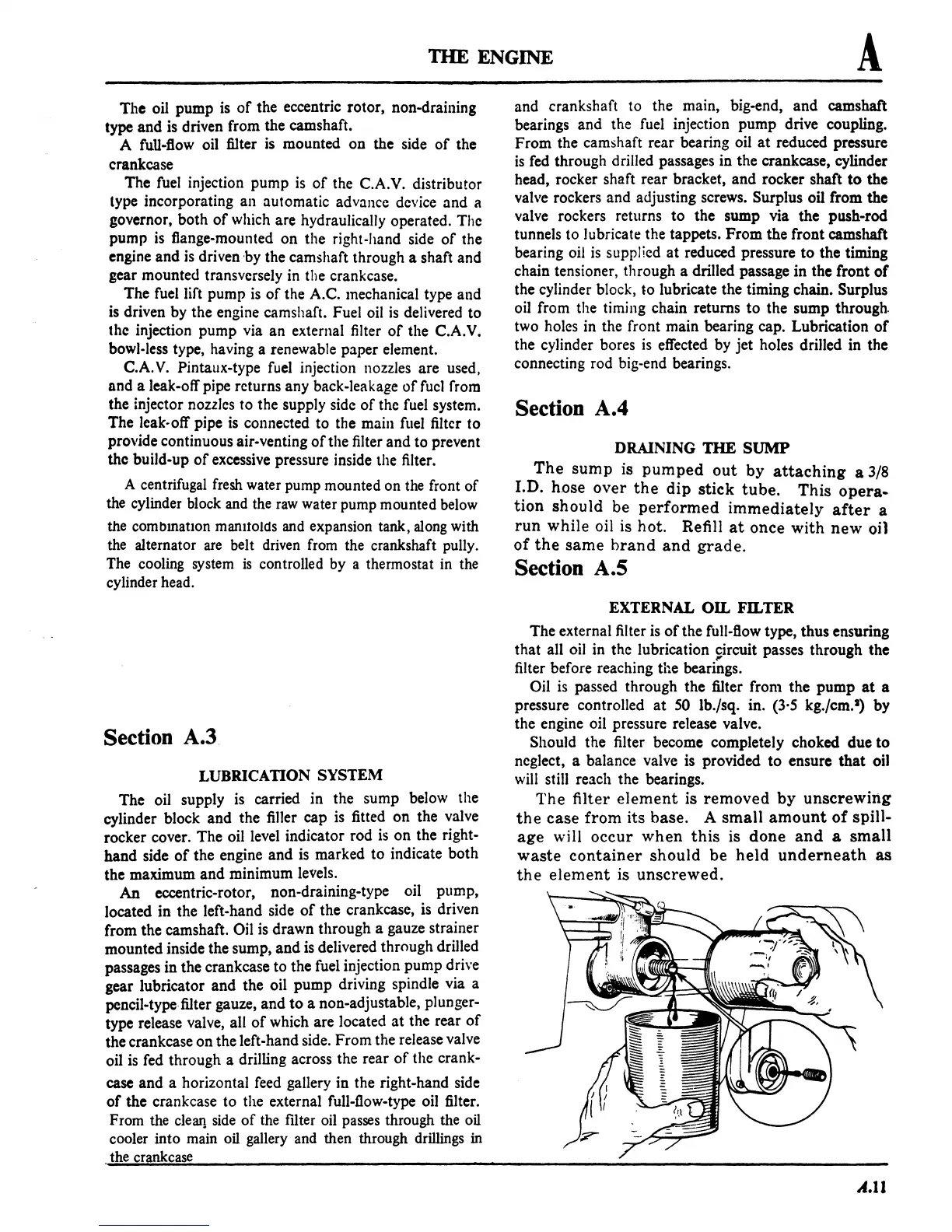
The
filter
element
is
removed
by
unscrewing
the
case
from
its
base.
A
small
amount
of
spill-
age
will
occur
when
this
is
done
and
a
small
waste
container
should
be
held
underneath
as
the
element
is
unscrewed.
A.11
 Loading...

