A
THE ENGINE
~
: : .
II;---H---
I,
I
f---G
--
-
l' F
-_
..
_
.•.
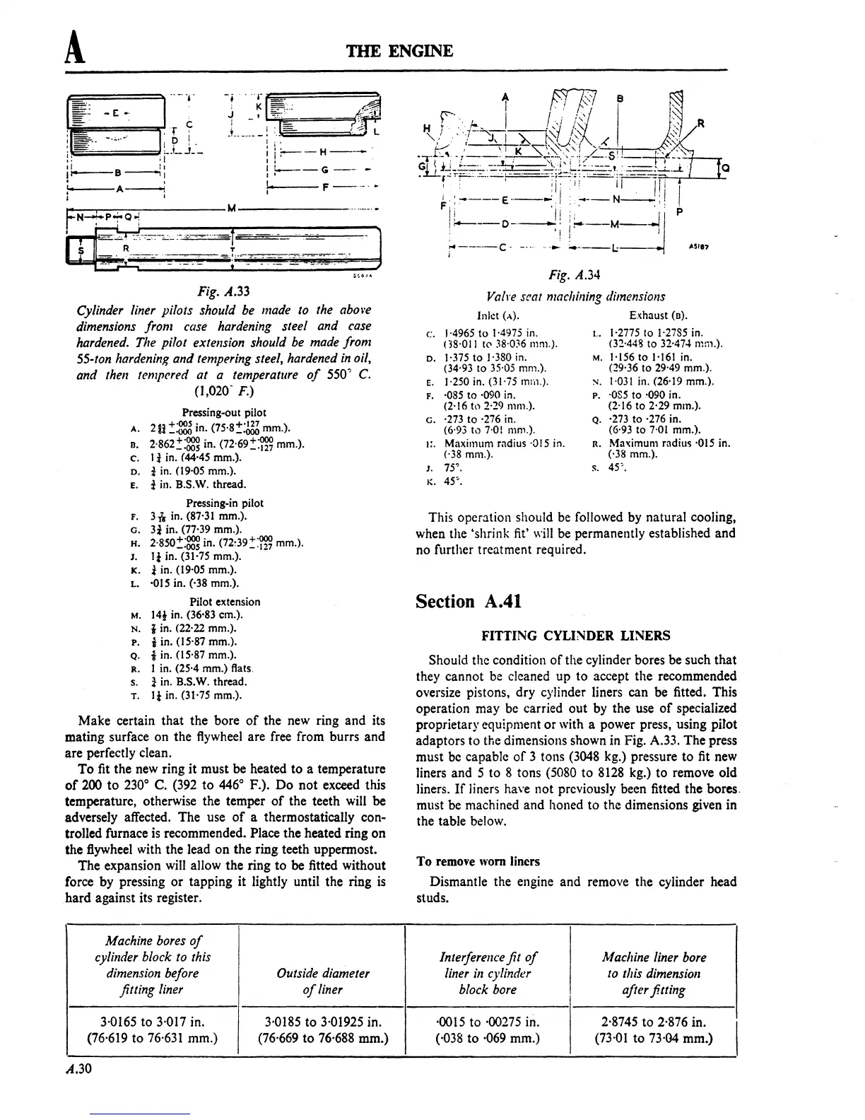
Fig.
A.33
Cylinder
liner
pilots should
be
made
10
the
above
dimensions
from
case
hardening
steel and
case
hardened.
The
pilot extension
should
be
made
from
55·ton
hardening
and
tempering
steel,
hardened
in
oil,
and
then
tempered at a
temperature
of
550'
C.
(1,020- F.)
Pressing-out pilot
A. 2 U
:~
in.
(75'8::~
mm.).
o.
2'862::~
in.
(72'69::m
mm.).
c. 1 i in. (44'45 mm.).
D.
i in. (19'05 mm.).
E. i in. B.S.W. thread.
Pressing-in pilot
F. 3 * in. (87'31 mm.).
o.
3i
in. (77·39 mm.).
H.
2'850::~
in.
(72:39::m
mm.).
J.
Ii
in. (31·75 mm.).
K.
i in. (19'05 mm.).
L.
'015 in. ('38 mm.).
Pilot extension
M.
14l
in. (36·83 em.).
N.
tin.
(22'22 mm.).
p.
i in. (15'87 mm.).
Q.
i in. (15'87 mm.).
R. I in. (25'4 mm.) flats.
s. ! in. B.S.W. thread.
T.
Ii
in. (31'75 mm.).
Make certain that the bore
of
the new ring and its
mating surface on the flywheel are free from burrs and
are perfectly clean.
To
fit the new ring
it
must be heated
to
a temperature
of
200
to
230
0
C.
(392
to
446
0
F.). Do
not
exceed this
temperature, otherwise the temper
of
the teeth
will
be
adversely affected. The use
of
a thermostatically con-
trolled furnace
is
recommended. Place the heated ring on
the flywheel with the lead on the ring teeth uppermost.
The expansion
will
allow the ring
to
be fitted without
force by pressing
or
tapping it lightly until the ring
is
hard against its register.
Machine
bores
of
cylillder
block
to
this
dimension
before
Outside
diameter
jilling
liner
of
liner
3·0165
to
3·017
in.
3·0185
to
3·01925
in.
(76·619
to
76·631
mm.)
(76'669
to
76·688
mm.)
A.30
Fig.
A.34
Va/re
seat
machining
dimensions
Inlet (A).
c.
1·4965
to
1·4975 in.
(38'011
to
38·036
111m.).
D.
1·375
to
1·380 in.
(34'93 to 35·05 mm.).
E.
1·250 in. (31·75
!TIm.).
F. ·085
to
·090 in.
(2'161l) 2·29 mm.).
G.
·273
to
·276 in.
(6'93 10
7·01
mm.).
I:.
Maximum radius ·015 in.
('38 mm.).
J.
75'.
K.
45'.
E.~haust
(D).
I.. 1·2775
to
1'2785 in.
(3:!·448 to 32·47-'
ml11.).
M.
1·156
to
1-161
in.
(:!9'36
to
29'49 mm.).
:-I.
1·031
in. (26'19 mm.).
p.
·OS5
to
'090 in.
(2'16
to
2'29 mm.).
Q. ·273
to
·276 in.
(6'93
to
7·01
mm.).
R. Maximum radius ·015 in.
('38 mm.).
s.
45'.
This operation should be followed by natural cooling,
when the 'shrink
fit'
will
be permanently established and
no further treatment required.
Section A.41
FITTING CYLINDER LINERS
Should
the condition
of
the cylinder bores be such that
they cannot be cleaned up
to
accept the recommended
oversize pistons, dry cylinder liners can be fitted. This
operation may be carried out by the use
of
specialized
proprietary equipment or with a power press, using pitot
adaptors to the dimensions shown in Fig. A.33. The press
must be capable
of
3 tons
(3048
kg.) pressure
to
fit new
liners and 5
to
8 tons
(5080
to
8128
kg.) to remove old
liners.
If
liners have not previously been fitted the bores.
must be machined and honed
to
the dimensions given in
the table below.
To
remove
worn
liners
Dismantle the engine and remove the cylinder head
studs.
Interferellce
jit
of
Machine
liner
bore
liner
ill
cylinder
to
this
dimensioll
block
bore
after fitting
·0015
to
·00275
ill.
2·8745
to
2·876
in.
I
('038 to
·069
mm.)
(73'01
to
73·04
mm.)
 Loading...

