D
THE FUEL SYSTEM
13----------~~~~~
12
1-_---2
1'1------3
4
IO---+~_
"'=:---
5
,_
......
9
6
8----
--------7
_
.793
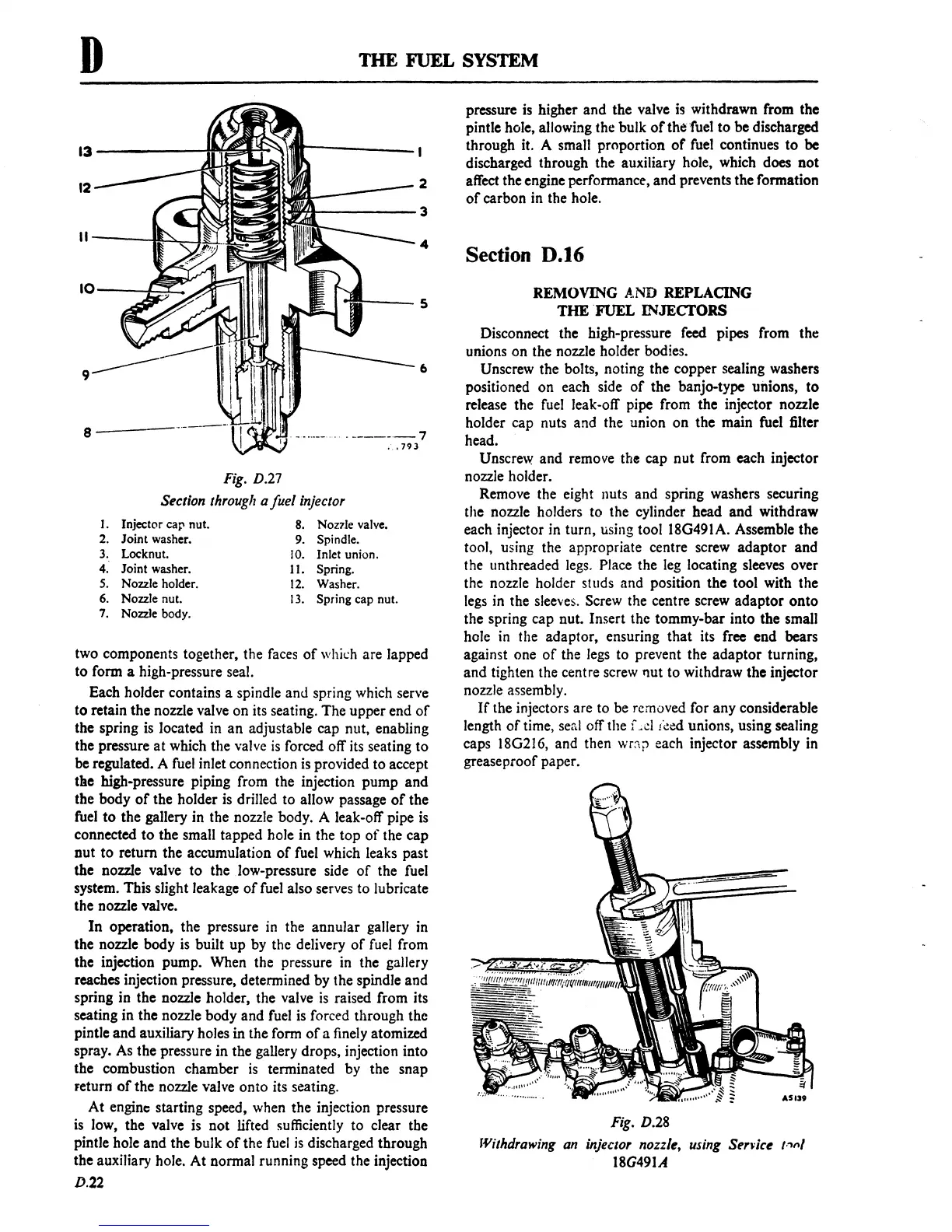
Fig.
D.27
Section
through a fuel injector
I.
Injector cap nut.
8.
Nozl.le
valve.
2.
Joint washer. 9. Spindle.
3.
Locknut.
10.
Inlet union.
4.
Joint washer. 11. Spring.
S.
Nozzle holder.
12.
Washer.
6.
Nozzle nut.
13.
Spring cap nut.
7.
Nozzle
body.
two components together, the faces
of
which are lapped
to form a high-pressure seal.
Each holder contains a spindle and spring which serve
to
retain the nozzle valve on its seating.
The
upper end
of
the spring is located in
an
adjustable cap nut, enabling
the pressure
at
which the valve
is
forced off its seating
to
be regulated. A fuel inlet connection
is
provided to accept
tile high-pressure piping from the injection pump
and
the body
of
the holder is drilled to allow passage
of
the
fuel
to
the gallery in the nozzle body. A leak-off pipe
is
connected
to
the small tapped hole in the top
of
the cap
nut
to
return the accumulation
of
fuel which leaks past
the nozzle valve
to
the Jow-pressure side
of
the fuel
system. This slight leakage
of
fuel also serves to lubricate
the nozzle valve.
In
operation, the pressure in the annular gallery in
the nozzle body
is
built up by the delivery
of
fuel from
the injection pump. When the pressure in the gallery
reaches injection pressure, determined by the spindle and
spring in the nozzle holder, the valve
is
raised from its
seating in the nozzle body and fuel
is
forced through the
pintle
and
auxiliary holes in the form
of
a finely atomized
spray. As the pressure in the gallery drops, injection into
the combustion chamber
is
terminated by the snap
Feturn
of
the nozzle valve onto its seating.
At
engine starting speed, when the injection pressure
is low, the valve is
not
lifted sufficiently to clear the
pintle hole and the bulk
of
the fuel
is
discharged through
the auxiliary hole.
At
normal running speed the injection
D.22
pressure
is
higher
and
the valve is withdrawn from the
pintle hole, allowing the bulk
of
the 'fuel
to
be discharged
through it. A small proportion
of
fuel continues
to
be
discharged through the auxiliary hole, which does
not
affect the engine performance, and prevents the formation
of
carbon in the hole.
Section D.16
REMOVING AND REPLACING
THE
'FUEL
INJECTORS
Disconnect the high-pressure feed pipes from the
unions on the nozzle holder bodies.
Unscrew the bolts, noting the copper sealing washers
positioned
on
each side
of
the banjo-type unions,
to
release the fuel leak-off pipe from the injector nozzle
holder cap nuts and the union
on
the main fuel filter
head.
Unscrew and remove
the cap
nut
from each injector
nozzle holder.
Remove the eight nuts and spring washers securing
the nozzle holders to the cylinder head
and
withdraw
each injector in turn, using tool 18G491A. Assemble the
tool, using the appropriate centre screw
adaptor
and
the unthreaded legs. Place the leg locating sleeves over
the nozzle holder studs and position the tool with the
legs in the sleeves. Screw the centre screw
adaptor
onto
the spring cap nut. Insert the tommy-bar into the small
hole in the adaptor, ensuring
that
its free end bears
against one
of
the legs to prevent the
adaptor
turning,
and
tighten the centre screw nut to withdraw the injector
nozzle assembly.
If
the injectors are to be removed for any considerable
length
of
time, seal off the f
-,d
t'~ed
unions, using sealing
caps 18G216, and then
wr:\t' each injector assembly in
grease proof paper.
Fig. D.28
Withdrawing an injector nozzle, using Service
,-.,,,/
18G491A
 Loading...

