I 2 Lay
the
engine
on
its side with
the
cylinder head slightly downwards.
13 Withdraw the dipstick.
14 Remove the sump.
15
Remove the oil pump and its drive
shaft.
16
Rotate
the camshaft
to
position all
the
tappets away from their cams.
17
Withdraw
the
camshaft.
18 Withdraw the tappets and retain their
order for refitting.
Refitting
19
Fit
the
tappets with their open ends
towards
the
cylinder head.
20
Fit the camshaft.
21
Fit the oil
pump
and
its drive shaft,
tightening the retaining nuts
to
16 Ibf
ft
(2.2 kgf
m,
22
Nm).
22
Fit the sump.
23 Fit the dipstick.
24
Place
the
engine in an upright
position.
25
Fit
the push-rods.
26 Fit the rocker shaft assembly, noting:
a Ensure
that
the
shim
is
fitted
under
both
centre brackets.
b Fit the locking pia te
to
the rear
bracket.
c Tighten
the
cylinder head nuts
to
75 Ibf ft
(l0.4
kgf m, 102 Nm) in
the sequence shown, using
tool
18G
694
to
reach
the
centre row.
d Tighten the rocker bracket nuts
to
25 Ibf ft (3.5 kgf
m,
34
Nm).
27
Fit the fuel lift pump.
28 Fit
the
camshaft locating plate.
29
Fit the camshaft gear, timing chain,
and timing gear cover,
see·12.65.12.
NOTE: Do
not
leave the crankshaft
pulley in position.
30
Adjust the valve rocker clearance, see
12.29.48.
31
Fit the rocker cover and its gasket.
32
NA
33 Run the engine for a minimum
of
5
miles, 8 km
or
I 5 mins and
on
return
slacken the cylinder head nuts
approximately
1
of
a
turn
in the
sequence shown before retightening
them
to
75lbfft
(lO.4kgfm,
102 Nm)
in the sequence shown. Check the
valve rocker clearances.
2 5
12
14
CAMSHAFT BEARINGS
Remove
and
refit 12.13.13
Service tools: 18G 55
A,
18G 123
A,
18G
123
B,
18G 123
E,
18G 123 F, 18G 123
L,
18G 123 T, 18G 123 AB, 18G 123
AC,
18G 123 AD, 18G 124
A,
18G 124
B,
18G
124
C,
18G 124 F, 18G 124
H,
18G 134,
18G 134 CQ, 18G 284, 18G
284
A,
18G
284
AC, 18G 694, 18G 1108, 18G 1195
Removing
I
NA
2 Drain the sump.
3
NA
4 Remove the
5 Remove the flywheel.
6 Remove
the
crankshaft rear oil seal
retainer.
7 Remove the bolts securing
the
gearbox
adaptor
plate and pull the
adaptor
plate
off
its two locating dowels.
8 Remove the two
adaptor
plate gaskets.
9 Remove the alternator.
10 Remove
the
high-pressure pipes from
the
injectors and pump.
II
Remove the injection pump drive oil
feed pipe.
I 2 Remove the timing chain and
the
camshaft gear, see 12.65.12.
13
Remove the camshaft locating plate.
14 Remove
the
chain vibration damper.
15
Remove the bolt securing each front
mounting bracket
to
the crankcase.
16 Remove the two bolts securing
the
front mounting plate
to
the crankcase.
17 Lift
off
the
front
mounting
plate,
complete with injection pump, front
mounting brackets, chain tensioner
stop-pin,
and
chain tensioner shoe.
18 Remove
the
fuel lift pump.
19 Withdraw
the
dipstick.
20
Release the dipstick
tube
from
the
cylinder head
nut
and withdraw
the
tube
from
the
crankcase.
21
Disconnect and remove No. I heater
plug.
22
Remove
the
rocker cover and gasket.
23 Remove the rocker shaft assembly,
noting the locking plate
on
the
rear
bracket and
the
shim
under
each
centre bracket.
24
Withdraw
the
push-rods, retaining
their order for refitting.
25 Remove the cylinder head nuts.
26 Lift
off
the
cylinder head.
NOTE:
The
combustion chamber
inserts may
drop
out
of
the cylinder
head as it
is
lifted; they MUST be
refitted in their original positions.
27
Remove
the
cylinder head gasket.
28
Lay the engine
on
its side with
the
cylinder head face slightly downwards.
29
Remove
the
sump.
30
Remove the oil
pump
and its drive
shaft.
31
Remove
the
big-end bearing caps and
bearing halves.
32
Remove
the
main bearing caps and
bearing halves, using tools 18G 284,
18G
284
A,
and 18G
284
AC.
33 Lift
out
the
crankshaft and remove
the
bearing and
thrust
washer halves.
34 Withdraw the connecting rod
and
piston assemblies.
35 Rotate
the
camshaft
to
position all the
tappets away from their cams.
36 Withdraw the camshaft.
37 Withdraw the tappets and retain their
order for refitting.
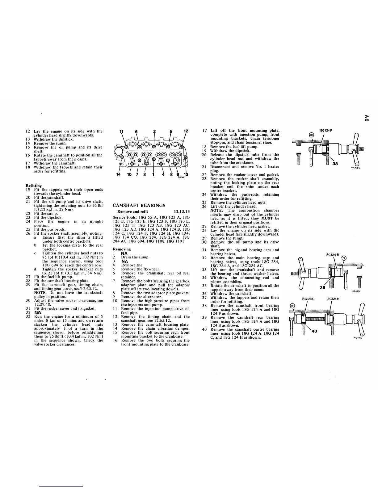
"38
Remove the camshaft front bearing
liner, using tools 18G 124 A and 18G
124 F
as
shown.
39
Remove
the
camshaft rear bearing
liner, using tools 18G 124 A and 18G
I
24
B
as
shown.
40
Remove the camshaft centre bearing
liner, using tools 18G 124
A,
18G 124
C,
and
18G 124 H as shown.
IBGI24F
,
IBGI24B
IBGI24C IBGI24H
INC49BC
i
INC497C.
INC496E
~
0)
 Loading...


