Refitting
NOTE: When fitting each new bearing liner
ensure
that
its oil holes are lined up with
those in the crankcase.
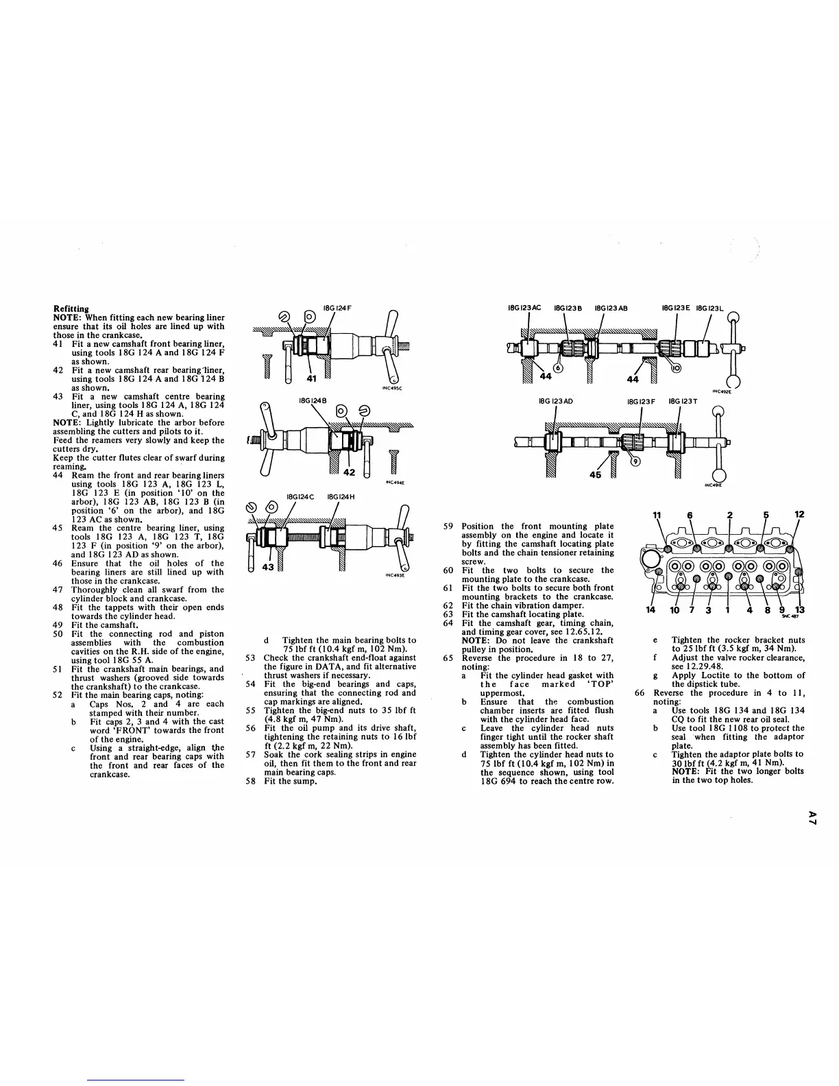
41 Fit a new camshaft front bearing liner,
using tools I
SG
124 A and ISG 124 F
as shown.
42
Fit a new camshaft rear bearing1iner,
using tools 18G 124 A and 18G
i
24
B
as
shown.
43 Fit a new camshaft centre bearing
liner, using tools
ISG 124
A,
ISG 124
C,
and ISG 124 H
as
shown.
NOTE: Lightly lubricate the arbor before
assembling the cutters and pilots
to
it.
Feed the reamers very slowly and keep
the
cutters dry.
Keep the
cutter
flutes clear
of
swarf during
reaming. .
44
Ream the front and rear bearing liners
using tools
ISG 123
A,
ISG 123
L,
ISG 123 E (in position
'10'
on
the
arbor),
ISG 123
AB,
ISG 123 B (in
position
'6'
on
the arbor), and ISG
1 23
AC
as
shown.
45
Ream the centre bearing liner, using
tools
ISG 123
A,
18G 123 T, ISG
123 F (in position
'9'
on
the
arbor),
and
ISG 123
AD
as shown.
46 Ensure that the oil holes
of
the
bearing liners are still lined up with
those in the crankcase.
47
Thoroughly clean all swarf from
the
cylinder block and crankcase.
4S Fit the tappets with their open ends
towards the cylinder head.
49
Fit the camshaft.
50 Fit the connecting rod and piston
assemblies with the combustion
cavities
on
the R.H. side
of
the engine,
using tool
ISG
55
A.
5 I Fit the crankshaft main bearings, and
thrust washers (grooved side towards
the crankshaft)
to
the crankcase.
52 Fit
the
main bearing caps, noting:
a Caps Nos. 2 and 4 are each
stamped with their number.
b Fit caps 2, 3 and 4 with
the
cast
word
'FRONT' towards the front
of
the engine.
c Using a straight-edge, align
t,he
front and rear bearing caps with
the front and rear faces
of
the
crankcase.
INC495C
I
INC494£
18GI24C
18GI24H
INC493E
d Tighten the main bearing bolts
to
75 Ibf ft
(l0.4
kgf
m,
102 Nm).
53 Check the crankshaft end-float against
the figure in DATA, and fit alternative
thrust washers
if
necessary.
54 Fit the big-end bearings and caps,
ensuring that the connecting rod and
cap markings are aligned.
55
Tighten the big-end nuts
to
35 Ibf ft
(4.S kgf
m,
47
Nm).
56 Fit the oil pump and its drive shaft,
tightening the retaining nuts
to
16 Ibf
ft (2.2 kgf
m,
22
Nm).
57
Soak the cork sealing strips in engine
oil, then
fit
them
to
the front and rear
main bearing caps.
58 Fit the sump.
18GI23AC
18G
123AD
59 Position the front mounting plate
assembly on the engine and locate it
by fitting the camshaft locating plate
bolts and the chain tensioner retaining
60
61
62
63
64
screw.
Fit the two bolts
to
secure
the
mounting plate
to
the crankcase.
Fit the two bolts
to
secure
both
front
mounting brackets
to
the crankcase.
Fit the chain vibration damper.
Fit the camshaft locating plate.
Fit the camshaft gear, timing chain,
and timing gear cover, see 12.65.12.
NOTE: Do not leave the crankshaft
pulley in position.
65 Reverse the procedure in 18
to
27,
noting:
,
a Fit the cylinder head gasket with
the
face
marked
'TOP'
uppermost.
b Ensure
that
the combustion
chamber inserts are fitted flush
with the cylinder head face.
c Leave the cylinder head nuts
finger tight until the rocker shaft
assembly has been fitted.
d Tighten the cylinder head nuts
to
75 Ibf ft (10.4 kgf m, 102 Nm) in
the sequence shown, using tool
18G 694
to
reach
the
centre row.
INC492E
18GI23F
18G
123T
INC49tE
e Tighten the rocker bracket nuts
to
25 Ibf ft (3.5 kgf
m,
34 Nm).
f Adjust the valve rocker clearance,
see 12.29.4S.
g Apply Loctite
to
the
bottom
of
the dipstick tube.
66 Reverse the procedure in 4
to
II,
noting:
a
Use
tools 18G 134 and 18G 134
CQ
to
fit the new rear oil seal.
b
Use
tool 18G
11
OS
to
protect the
seal 'when fitting the adaptor
plate.
c Tighten the adaptor plate bolts
to
30 Ibf ft (4.2 kgf
m,
41
Nm).
NOTE: Fit the two longer bolts
in the two
top
holes.
»
"'"
 Loading...


