20
Remove
the
oil pump and its drive
shaft.
21
Remove the big-end bearing caps and
bearing halves.
NOTE:
If
the crankshaft has
to
be
rotated, be careful not to apply any
force which could cause damage
if
a
piston touches a valve.
22 Remove the main bearing caps and
bearing halves, using tools 18G 284
and 18G 284
AC
on
the front and rear
caps if necessary.
23 Lift
out
the crankshaft and remove
the bearing and thrust washer halves.
24
Remove the crankshaft gear.
25 Remove the crankshaft keys and lift
off
the
shim(s}.
Refitting
26 Fit the shim(s}, keys and gear
to
the
crankshaft.
27 Fit the crankshaft, main bearings, and
thrust washers (grooved side towards
the crankshaft)
to
the
crankcase.
28 Fit
the
main bearing caps, noting:
a Caps Nos. 2 and 4 are each
stamped with their number.
b Fit caps 2, 3, and 4 with
the
cast
word 'FRONT' towards the front
of
the engine.
c Using a straight-edge, align the
front and rear bearing caps with
the front and rear faces
of
the
crankcase.
d Tighten the main bearing bolts
to
751bfft
(l0.4
kgf m, 102 Nm).
29 Check the crankshaft end-float against
the figure in
OAT
A,
and fit alternative
thrust washers
if
necessary.
30 Fit the big-end bearings and caps,
ensuring that the connecting rod and
cap markings are aligned.
31
Tighten the big-end nuts to 35 Ibf ft
(4.8 kgf
m,
47
Nm).
DATA
Main
journal diameter
.............
.
Crankpin diameter
.•.•.•....•.....
Clearance in bearings Uournals and crank-
pin}
.••.......••.••..•......
Undersizes Uournals and crankpins}
.....
Crankshaft end-float
..•••..........
Thrust washer thicknesses
..........
.
32 Fit the oil pump and its drive shaft,
tightening the retaining nuts
to
161bf
ft (2.2 kgf m, 22 Nm).
33 Soak the cork sealing strips in engine
oil, then fit them
to
the
front and rear
main bearing caps.
34 Fit the sump.
35 Fit the dipstick.
36 Position
the
front mounting plate
assembly on
the
engine and locate it
by
fitting the camshaft locating plate
bolts and the chain tensioner retaining
screw.
37 Fit the two bolts to secure the front
mountig plate
to
the crankcase.
38 Fit the two bolts
to
secure
both
front
mounting plate
to
the
crankcase.
39 Fit the chain vibration damper.
40
Fit the camshaft locating plate.
41
Fit the camshaft gear, timing chain,
and timing gear cover, see 12.65.12.
NOTE:
00
not
leave the crankshaft
pulley in position.
42
Reverse the procedure in 4 to
II,
noting:
a
Use
tools 18G 134 and 18G 134
CQ
to
fit
the
new rear oil seal.
b
Use
tool
18G 1108
to
protect
the
seal when fitting
the
adaptor
plate.
c Tighten the adaptor plate bolts
to
30 Ibf ft (4.2 kgf
m,
41 Nm). .
NOTE: Fit the two longer bolts
in the two top holes.
d Tighten the oil seal retainer bolts
to
20
Ibf
ft (2.8 kgf
m,
27 Nm).
e Tighten the flywheel bolts
to
40
Ibf ft (5.5 kgf m, 54 Nm).
2.1262 to
2.1270 in (54.01
to
54.03 mm)
1.8759
to
1.8764 in (47.64
to
47.66 mm)
0.001
to
0.0027 in (0.03 to 0.07 mm)
0.010 in (0.25 mm)
0.001
to
0.0055 in (0.03
to
0.14 mm)
0.0885
to
0.0905 in (2.25
to
2.30 mm),
0.091
to
0.093 in (2.31
to
2.36 mm) and
0.0935 to 0.0955 in (2.37
to
2.43 mm)
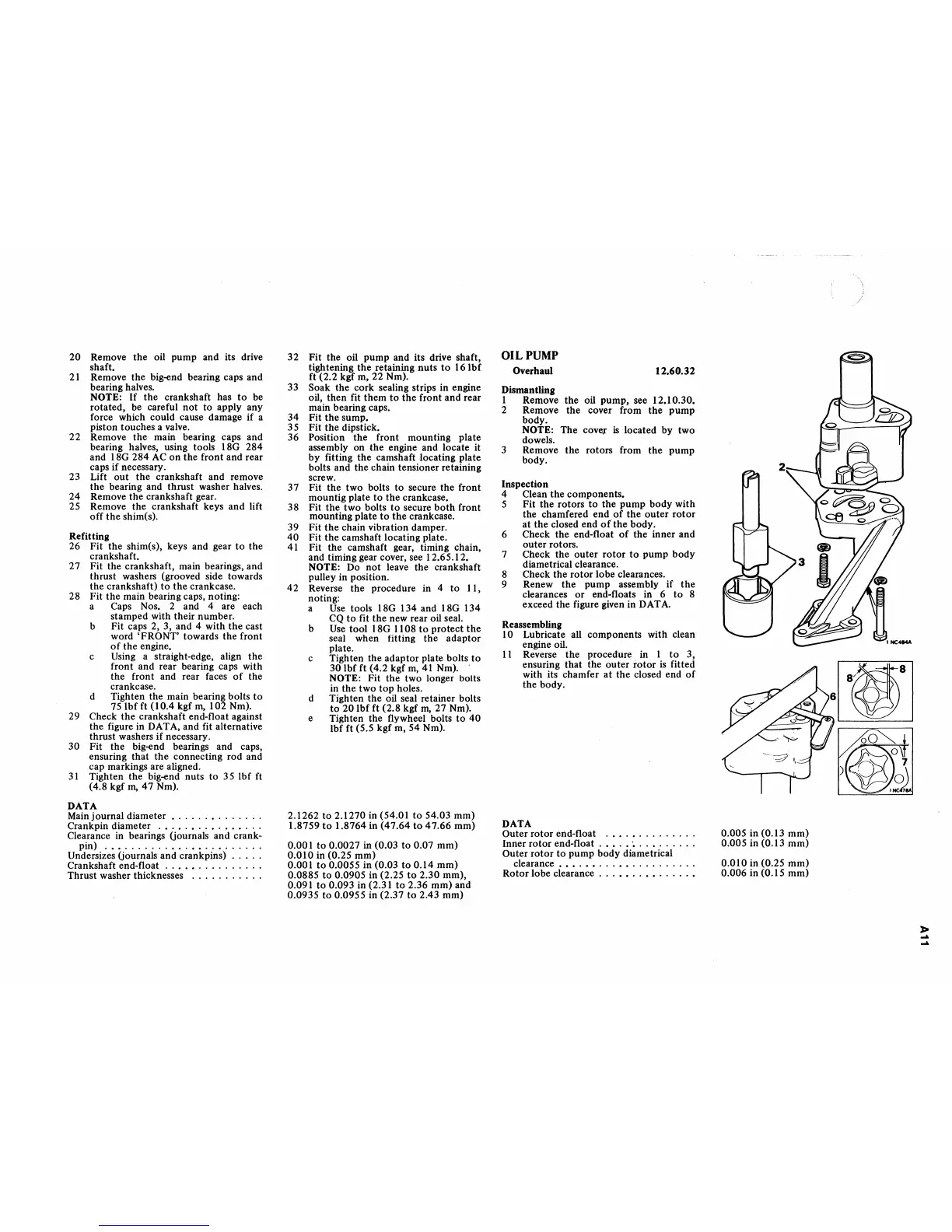
OIL
PUMP
Overhaul
Dismantling
12.60.32
I Remove the oil pump, see 12.10.30.
2 Remove the cover from the pump
body.
NOTE: The
cove.r
is
located by two
dowels.
3 Remove the rotors from the pump
body.
Inspection
4 Clean the components.
5 Fit the rotors
to
the pump body with
the chamfered end
of
the
outer
rotor
at
the closed end
of
the body.
6 Check the end-float
of
the inner and
outer rotors.
7 Check the
outer
rotor
to
pump body
diametrical clearance.
8 Check the rotor lobe clearances.
9 Renew the pump assembly if
the
clearances
or
end-floats in 6
to
8
exceed the figure given in
OAT
A.
Reassembling
10 Lubricate all components with clean
engine oil.
II
Reverse
the
procedure in I
to
3,
ensuring that the
outer
rotor
is
fitted
with its chamfer
at
the closed end
of
the body.
DATA
Outer rotor end-float
.••.•.........
Inner rotor end-float
.••.•
~
..•......
Outer
rotor
to
pump body diametrical
clearance
•••.••...••..........
Rotor lobe clearance
...••..••.....•
~
'HC4MA
~lIIl
0.005 in (0.13 mm)
0.005 in (0.13 mm)
0.010 in (0.25 mm)
0.006 in {0.15
mm}
»
~
~
 Loading...


