16
16
ENGINE
FRONT
MOUNTING
PLATE
GASKET
Remove
and
refit
12.25.10
Removing
I Remove
the
timing chain
and
the
camshaft gear, see 12.65.12.
2 Remove
the
camshaft locating plate.
3 Remove
the
chain vibration damper.
4 Remove
the
alternator.
5 Disconnect
the
thermal
transmitter
and
move
the
wiring harness aside.
6 Disconnect
the
supply
lead from
the
heater
plugs.
7 Disconnect
the
fuel
return
pipe from
the
injection
pump.
8 Disconnect
the
fuel supply pipe from
the
injection
pump.
9 Disconnect
the
stop
control
cable
from
the
injection
pump.
10 Disconnect
the
throttle
cable from
the
injection
pump
lever.
II
Remove the injection
pump
drive oil
feed pipe.
12 Disconnect
the
high-pressure pipes
from
the
injectors.
13 Remove
the
two
bolts
and
washers
securing the front moullting plate
to
the
crankcase.
14 Lift
off
the
front
mounting
plate,
complete
with injection
pump,
front
mountings, chain tensioner stop-pin,
and
chain tensioner shoe.
IS.,
16 NA
17'/
18 Remove
the
front
mounting
plate
gasket
Refitting
19
Fit
the
front
mounting
plate gasket.
20
Position
the
front
mounting
plate
assembly
on
the
engine
and
locate it
by
fitting
the
camshaft
locating
plate
bolts
and
the
chain
tensioner
retaining
screw.
21
Reverse
the
procedure
in I
to
16,
noting:
a With
the
throttle
cable
connected
ensure
that
the
injection
pump
throttle
lever
is
operated
through
its full range
of
movement
by
the
throttle
pedal.
b When
the
stop
control
cable
is
connected,
ensure
that
the
stop
control
has sufficient travel
22 Bleed
the
fuel system, see 19.50.07.
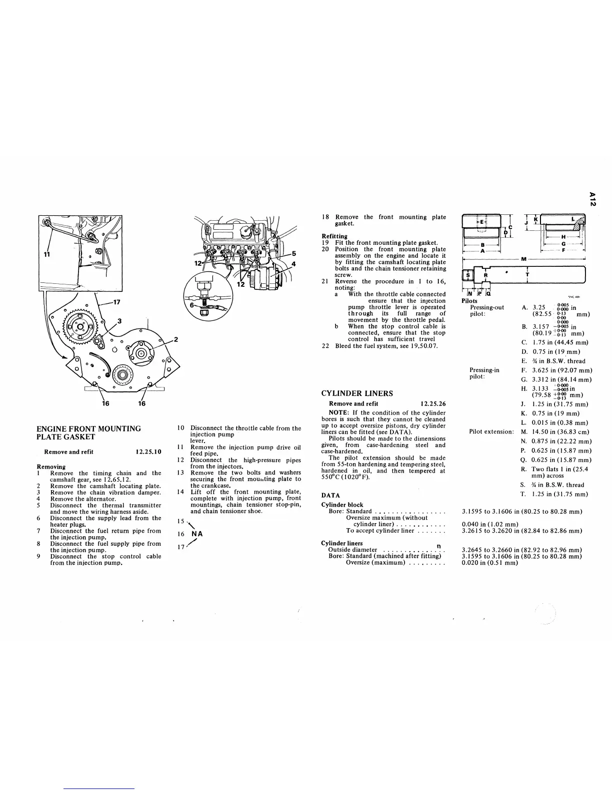
CYLINDER LINERS
Remove
and
refit
12.25.26
NOTE:
If
the
condition
of
the
cylinder
bores
is
such
that
they
cannot
be cleaned
up
to
accept oversize pistons, dry cylinder
liners can be fitted (see DATA).
Pilots should be made
to
the
dimensions
given, from case-hardening steel
and
case-hardened.
The
pilot extension should be
made
from
55-ton
hardening
and
tempering steel,
hardened
in oil,
and
then
tempered at
550°C
(l020°F).
DATA
Cylinder block
Bore:
Standard
.•...............
Oversize maximum
(without
cylinder liner)
.........
.
To
accept
cylinder
liner
Cylinder liners n
Outside
diameter
...........
.
Bore:
Standard
(machined
after
fitting)
Oversize
(maximum)
........
.
" M
~
· t 1
J\I
f>
Q
Pilots
Pressing-out
pilot:
"'~4ft'
A.
3.25
8:~
in
(82.55'
0·13
mm)
0'00
0'000
B.
3.
IS
7
-0'005
in
(80.19
:"g:r:
mm)
C.
1.75 in
(44.45
mm)
D.
0.75
in
(19
mm)
E.
34
in B.S.
W.
thread
»
....
I\)
Pressing-in
pilot:
F. 3.625 in
(92.07
mm)
G.3.312in(84.14mm)
Pilot extension:
, 0'000
H.
3.133
-0'005
in
(79.58
:::g:r:
mm)
J. 1.25 in
(31.75
mm)
K.0.75in(l9mm)
L.
0.015
in
(0.38
mm)
M.
14.50 in
(36.83
em)
N.
0.875
in
(22.22
mm)
P.
0.625 in
(15.87
mm)
Q.
0.625
in
(15.87
mm)
R.
Two
flats I in
(25.4
mm)
across
S.
34
in B.S.W.
thread
T. 1.25 in (31.75
mm)
3.1595
to
3.1606
in
(80.25
to
80.28
mm)
0.040
in (1.02
mm)
3.2615
to
3.2620
in
(82.84
to
82.86
mm)
3.2645
to
3.2660
in
(82.92
to
82.96
mm)
3.1595
to
3.1606
in
(80.25
to
80.28
mm)
0.020
in (0.51
mm)