CYLINDER HEAD
Overhaul
12.29.19
Service tools: 18G 27, 18G 29, 18G 45,
18G 167, 18G 167
A,
18G 167
B,
18G 167
C,
18G 174, 18G
1741\,
18G 174
B,
18G
174
C,
18G 174
D,
18G 284, 18G
284
P
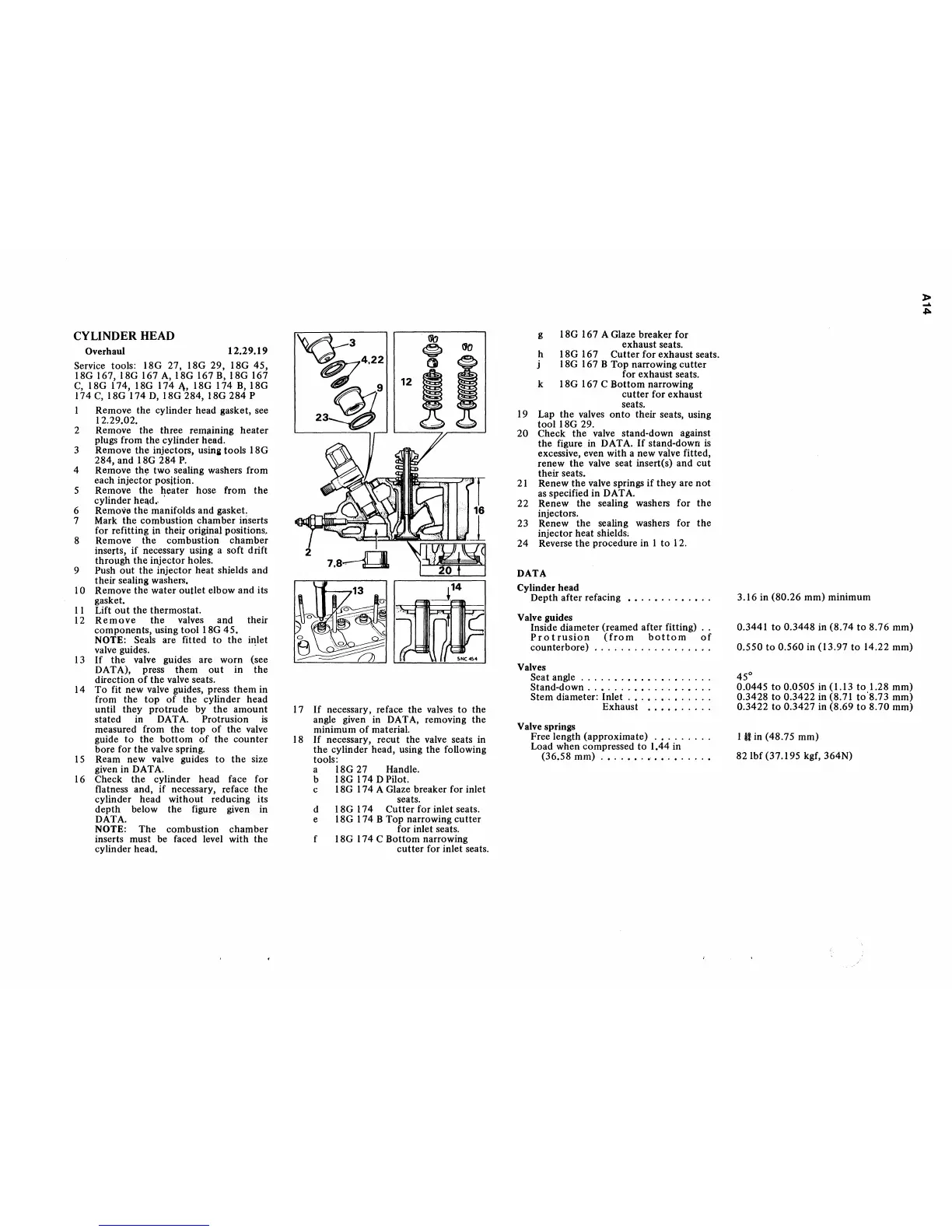
I Remove the cylinder head gasket, see
12.29.02.
2 Remove the three remaining
heater
plugs from the cylinder head.
3 Remove
the
injectors, usinl: tools 18G
284, and 18G
284
P.
4 Remove
the
two sealing washers from
each injector position.
5 Remove
the
heater hose from
the
cylinder head
•..
6 Remove
the
manifolds and gasket.
7 Mark the combustion chamber iriserts
for refitting jn their original positions.
8 Remove
the
combustion
chamber
inserts,
if
necessary using a soft drift
through
the
injector holes.
9 Push
out
the
injector heat shields and
their
sealing washers.
10 Remove
the
water
outlet
elbow and its
gasket.
II
Lift
out
the
thermostat.
12
Remove
the
valves and their
components, using
tool
18G
45.
NOTE: Seals are fitted
to
the
inlet
valve guides.
-
13
If
the
valve guides are worn (see
DATA), press
them
out
in
the
direction
of
the
valve seats.
14
To
fit new valve guides, press
them
in
from
the
top
of
the
cylinder head
until they
protrude
by
the
amount
stated in DATA. Protrusion
is
measured from
the
top
of
the
valve
guide
to
the
bottom
of
the
counter
bore for
the
valve spring.
15
Ream new valve guides
to
the
size
given in DATA.
16 Check
the
cylinder head face for
flatness and, if necessary, reface
the
cylinder head without reducing its
depth
below
the
figure given in
DATA.
NOTE:
The
combustion
chamber
inserts must be faced level with
the
cylinder head
o
\'J{)
17
If
necessary, reface the valves
to
the
angle given in DATA, removing
the
minimum
of
material.
18
If
necessary, recut the valve seats in
the
cylinder head, using
the
following
tools:
a 18G 27 Handle.
b 18G 174 DPilot.
c 18G 174 A Glaze breaker for inlet
seats.
d 18G 174
Cutter
for inlet seats.
e 18G 174 B Top narrowing
cutter
for inlet seats.
18G 174 C
Bottom
narrowing
cutter
for inlet seats.
g 18G 167 A Glaze breaker for
exhaust seats.
h 18G 167
Cutter
for
exhaust seats.
18G 167 B
Top
narrowing
cutter
for exhaust seats.
k 18G 167 C
Bottom
narrowing
cutter
for exhaust
seats.
19 Lap
the
valves
onto
their seats, using
tool 18G 29.
20 Check
the
valve stand-down against
the
figure in DATA.
If
stand-down
is
excessive, even with a new
va1ve
fitted,
renew
the
valve seat insert(s) and
cut
their seats.
21
Renew
the
valve springs
if
they
are
not
as specified in DATA.
22
Renew
the
sealing washers
for
the
injectors.
23 Renew
the
sealing washers for
the
injector heat shields;
24
Reverse
the
procedure in I
to
12.
DATA
Cylinder
head
Depth
after
refacing
Valve guides
Inside diameter (reamed after fitting)
Protrusion
(from
bottom
of
counterbore)
.................
.
Valves
Seat angle
..............•.....
Stand-down
..•.....•......•...
Stem
diameter: Inlet
............
.
Exhaust
..•.......
Valve springs
Free length (approximate)
........
.
Load when compressed
to
1.44 in
(36.58 mm)
....••.•...•.....
3.16 in
(80.26
mm) minimum
0.3441
to
0.3448 in (8.74
to
8.76 mm)
0.550
to
0.560
in (13.97
to
14.22 mm)
45°
0.0445
to
0.0505 in (1.13
to
1.28 mm)
0.3428
to
0.3422
in (8.71
to'8.73
mm)
0.3422
to
0.3427 in
(8.69
to
8.70
mm)
I
it
in (48.75 mm)
82 Ibf (37.195 kgf,
364N)
~
....
~
 Loading...


