VALVE CLEARANCE
Check and adjust 12.29.48
Checking
I Remove the rocker cover
ana
gasket.
2 Check, and
if
necessary adjust, the
clearance between the rocker arms and
valve stems against the figure in
DATA, working in the following
order:
Check:
No. I valve with
No.8
valve fully open.
3
" 6
" 5 4
2 7
" S " I
,,6
,,3
4 " 5
" 7 " 2
DATA
Valve rocker clearance (cold)
ROCKER
SHAFf
ASSEMBLY
Remove and refit
Service tool: ISG 694
Removing
I
NA
2 Drain the cooling system.
12.29.54
3 Remove the rocker cover and gasket.
4
Slacken evenly and remove the eight
nuts retaining
the
rocker shaft
brackets.
5 Remove the locking plate from
the
rocker shaft rear bracket.
6 Remove
the
rocker shaft assembly and
the
shim under each centre bracket.
4
2,
I
be...j
3
4HC104A
Adjusting
3
Slacken the locknut.
4 Rotate the adjusting screw
to
set the
clearance.
5 Hold the adjusting screw against
rotation and tighten the locknut.
6 Fit the rocker cover and gasket.
0.017 in (0.43 mm)
'SNC
.,7
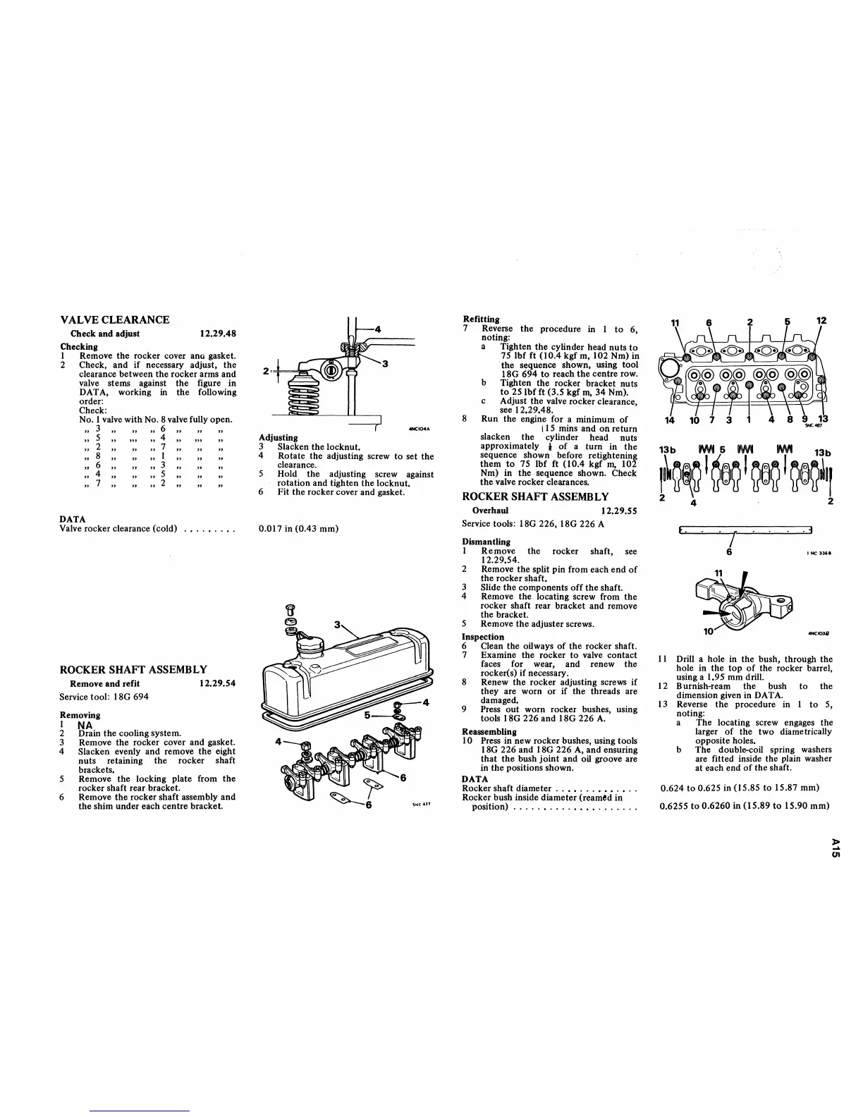
Refitting
7 Reverse
the
procedure in I
to
6,
noting:
a Tighten the cylinder head nuts
to
75
Ibfft
(10.4 kgf m, 102 Nm) in
. the sequence shown, using tool
ISG 694
to
reach
the
centre row.
b Tighten the rocker bracket nuts
to
251bf
ft (3.5 kgf
rn,
34
Nm).
c Adjust the valve rocker clearance,
see 12.29.4S.
S Run the engine for a minimum
of
115
mins and
on
return
slacken the cylinder head nuts
approximately
t
of
a turn in
the
sequence shown before retightening
them
to
75 Ibf ft (10.4 kgf
rn,
102
Nm)
in
the sequence shown. Check
the
valve rocker clearances.
ROCKER
SHAFf
ASSEMBLY
Overhaul 12.29.55
Service tools: ISG 226, ISG 226 A
Dismantling
I Remove the rocker shaft, see
12.29.54.
2 Remove the split pin from each
end
of
the rocker shaft.
3
Slide the components
off
the
shaft.
4 Remove the locating screw from
the
rocker shaft rear bracket and remove
the bracket.
5 Remove
the
adjuster screws.
Inspection
6 Clean the oilways
of
the rocker shaft.
7 Examine the rocker to valve contact
faces for wear, and renew the
rocker(s)
if
necessary.
S Renew
the
rocker adjusting screws
if
they are worn
or
if
the
threads
are
damaged.
9
Press
out
worn rocker bushes, using
tools
ISG 226 and ISG 226
A.
Reassembling
10 Press in new rocker bushes, using tools
ISG 226 and ISG 226
A,
and ensuring
that
the
bush
joint
and oil groove are
in
the
positions shown.
DATA
Rocker shaft diameter
..••...•••.•..
Rocker bush inside diameter (reamed in
position)
.....•....••••.......
6 12
13b
PM·
6
W\I1
MIt
13b
I~Q~
I
~Q
I
~
I
Q~Q.II
2 4 . 2
t.
_
.1
I
6 INC
....
_10311
II
Drill a hole in the bush, through the
hole in the
top
of
the rocker barrel,
using a 1.95 mm drill.
I 2 Burnish-ream the bush
to
the
dimension given in DATA.
13
Reverse
the
procedure in I
to
5,
noting:
a The locating screw engages the
larger
of
the two diametrically
opposite holes.
b The
doubl&ocoil
spring washers
are fitted inside the plain washer
at each end
of
the shaft.
0.624
to
0.625 in (15 .S5
to
15.S7 mm)
0.6255
to
0.6260 in
(l5.S9
to
15.90 mm)
»
...
U1