OIL
PRESSURE RELIEF VALVE
Remove and refit
Service tool: 18G 69
Removing
.1
INA
12.60.56
2 Remove the valve cap washer from
the
rear
of
the L.H. side
of
the crankcase.
3 Withdraw the spring from
the
crankcase.
4 Withdraw the valve
plunser, using tool
18G 69.
Refitting
5
If
the valve plunger
is
pitted,
or
is
not
seating correctly, lap the plunger
onto
its seating, using tool 18G 69.
If
lapping fails
to
correct
the
fault,
renew the plunger and ensure that
the
new plunger seats correctly.
6 Renew the spring
if
it
is
not
as
specified in DATA.
7 Reverse the procedure in 1
to
4.
DATA
Relief valve spring:
Free length
.......•.•.••...•..
Load when compressed to 2.16 in
(54.77 mm)
.••.••.••.•..•...
t~~~)
Qg)i&m-;l
~
4
-..."
I
INC
oue
3 in (76 mm)
15.5
to
16.51bf (7.0
to
7.4 kgf,
69
to
73
N)
TIMING GEAR COVER
OIL
SEAL
Remove and refit 12.65.05
Service tools: 18G ·98
A,
18G 134, 18G
134
BD
Removing
I
lNA
2 Slacken the alternator mounting boIts
and remove the fan belt.
3 Remove the
. water pump
pulley.
4 Remove the crankshaft pulley, using
tool 18G 98
A.
5 Remove the timing gear cover and
gasket.
6 Remove the oil seal from the timing
cover.
Refitting
7 Fit the new oil seal
to
the timing gear
cover, using tools 18G 134 and 18G
134
BD.
8 Fit the timing gear cover and gasket,
using the crankshaft pulley
to
centralize the oil seal
on
the
crankshaft.
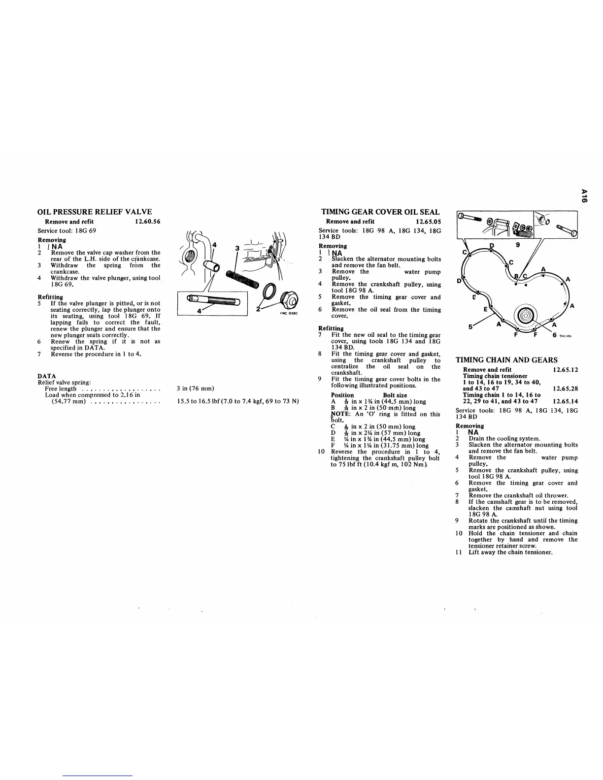
9 Fit the timing gear cover boIts in the
following illustrated positions.
Position Bolt size
A
fa-
in x I % in (44.5 mm) long
B
1\
in x 2 in (50 mm) long
l'lOTE: An
'0'
ring
is
fitted on this
'bolt.
C
1\
in x 2 in (50 mm) long
D
1\
in x
2Y..
in (57 mm) long
E
Y..
in x
1%
in (44.5 mm) long
F
Y..inxlY..in(31.75mm)long
10 Reverse the procedure in I
to
4,
tightening the crankshaft pulley boIt
to
751bf
ft (10.4 kgf
m,
102
Nm~
~~-~;;
-,
J
TIMING CHAIN AND GEARS
Remove and refit 12.65.12
Timing chain tensioner
1 to 14, 16 to 19, 34 to
40,
and
43
to
47
12.65.28
Timing chain 1 to 14, 16
to
22,29
to
41, and
43
to
47
12.65.14
Service tools: 18G 98
A,
18G 134, 18G
134
BD
Removing
I
NA
2 Drain
the
cooling system.
3 Slacken the alternator mounting bolts
and remove the fan belt.
4 Remove
the
water pump
pulley.
5 Remove the crankshaft pulley, using
tool 18G 98
A.
6 Remove the timing gear cover and
gasket.
7 Remove the crankshaft oil thrower.
8
If
the camshaft gear is to be removed,
slacken the camshaft
nut
using tool
18G 98
A.
9 Rotate the crankshaft until
the
timing
marks are positioned as shown.
10 Hold the chain tensioner and chain
together by hand and remove
the
tensioner retainer screw.
11
Lift away the chain tensioner.
»
...
0)