o
~~
~f?11
1--\.
~;;~
-I
},
39
29
/
!.~
.
.;;:~
C
30
SHe
"56
A
1 2
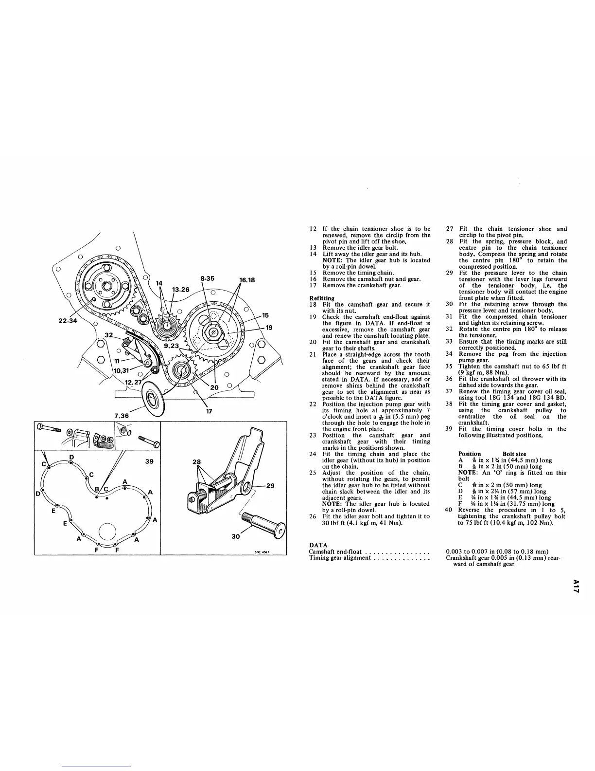
If
the chain tensioner shoe is to be
renewed, remove the circlip from the
pivot pin and lift
off
the shoe.
13
Remove the idler gear bolt.
14 Lift away the idler gear and its hub.
NOTE: The idler gear hub
is
located
by a roll-pin dowel.
15
Remove the timing chain.
16 Remove the camshaft
nut
and·gear.
17 Remove the crankshaft gear.
Refitting
18 Fit the camshaft gear and secure it
with its nut.
I 9 Check the camshaft end-float against
the figure in DATA.
If
end-float
is
excessive, remove
the
camshaft gear
and renew
the
camshaft locating plate.
20 Fit the camshaft gear and crankshaft
gear
to
their shafts.
21
Place a straight-edge across the
tooth
face
of
the gears and check their'
alignment; the crankshaft gear face
should be rearward by the amount
stated in DATA.
If
necessary, add or
remove shims behind the crankshaft
gear to set the alignment
as
near as
possible
to
the DATA figure.
22 Position the injection pump gear with
its timing hole
at
approximately 7
o'clock and insert a
* in (5.5 mm) peg
through the hole
to
engage the hole in
the engine front plate.
23 Position the camshaft gear and
crankshaft gear with their timing
marks in the positions shown.
24 Fit the timing chain and place the
idler gear (without its hub) in position
on
the chain.
25 Adjust the position
of
the chain,
without rotating the gears, to permit
the idler gear hub
to
be fitted. without
chain slack between the idler and its
adjacent gears.
NOTE: The idler gear hub
is
located
by a roll-pin dowel.
26 Fit the idler gear bolt and tighten it
to
30
lbf
ft (4.1 kgf
m,
41
Nm).
DATA
Camshaft end-float . . . . . . . . . . . . . . . .
Timing gear alignment
...•.•.•...•.•
27 Fit the chain tensioner shoe and
circlip
to
the pivot pin.
28 Fit the spring, pressure block, and
centre pin
to
the chain tensioner
body. Compress the
~ringand
rotate
the
centre pin 180
to
retain the
compressed position.
29 Fit the pressure lever
to
the chain
tensioner with the lever
legs
forward
of
the tensioner body, i.e.
the
tensioner body will contact the engine
front plate when fitted.
30 Fit the retaining screw through the
pressure lever and tensioner body.
31
Fit the compressed chain tensioner
and tighten its retaining screw.
32 Rotate the centre pin
180
0
to
release
the tensioner.
33 Ensure that the timing marks are still
correctly positioned.
34 Remove the peg from the injection
pump gear.
35 Tighten
the
camshaft
nut
to
65 Ibf
ft
(9 kgf m, 88 Nm).
36 Fit the crankshaft oil thrower with its
dished side towards the gear.
37 Renew the timing gear cover oil seal,
using tool 18G 134 and 18G 134
BD.
38 Fit the timing gear cover and gasket,
using the crankshaft pulley
to
centralize the oil seal
on
the
crankshaft.
39 Fit the timing cover bolts in the
following illustrated positions.
Position Bolt size
A
·rw
in x I * in (44.5 mm) long
B
-A.
in x 2 in
(50
mm) long
NOTE: An
'0'
ring
is
fitted on this
bolt
C
*in
x 2 in (50 mm) long
D
* in
)(
2U.
in (57 mm) long
E
U.
in x I * in (44.5 mm) long
F
U.inxlU.in(31.75mm)long
40
Reverse the procedure in I
to
5,
tightening the
crankshaft pulley bolt
to
75lbf
ft (10.4 kgf
m,
102 Nm).
0.003
to
0.007 in (0.08 to 0.18 mm)
Crankshaft gear
0.005 in (0.13 mm) rear-
ward
of
camshaft gear
»
....
.....
 Loading...


