FUEL FILTER ELEMENT
Remove and refit
19.25.07
Removing
1
Support
the filter base and unscrew
the
centre bolt in
the
filter head.
2 Detach the filter base.
3 Remove the element, using a twisting
motion.
4 Remove the seals from the filter base
and
filter head.
Refitting
5 Clean the filter base.
6 Reverse the procedure in
I
to
4,
using
a new element and seals.
7 Bleed
the
fuel system, see 19.50:07.
HYDRAULIC TYPE ONLY
INJECfION
PUMP
Remove
and
refit
Ti'lliUg -
check
and
adjust
1
to
16
and
21
to
38
19.30.07
19.30.01
Service tools:
AMK
9990,
MS
67 A
Removing
I Slacken
the
alternator
mounting
bolts
and
remove"the fan belt.
2 Remove
the
alternator.
3 Disconnect the fuel return pipe from
the
injection
pump.
4 Disconnect the fuel supply pipe from
the
injection pump.
5 Disconnect
the
stop
control
cable
from
the
injection
pump.
6 Disconnect
the
throttle
cable from
the
injection
pump
"
7 l>isconnect
the
lead from
the
fuel
preSSIre
ulte.
8 Remove the injection
pump
stop
lever
return spring.
9 Remove Nos. 3
and
4 injector pipes.
10 Remove Nos. I
and
2 injector pipes.
II
Remove the three nuts and washers
securing the injection
pump
and
withdraw the injection
pump
from
the
engine.
NOTE:
The
lower
nut
also secures the
anchor
bracket for
the
stop
lever
return
spring.
12 Withdraw the injection
pump
torsion
bar.
13
Remove the injection
pump
gasket.
14-
20
IIA
~~
SN::46S
Refitting
21
Rotate
the
crankshaft until
the
master
spline in
the
injection
pump
drive
is
in
the
12
o'clock
position.
22 Insert timing pin AMK
9990
into
the
timing hole in
the
gearbox
adaptor
plate.
The
hole
is
situated below
the
sump
flange
on
the
RH side.
23 Maintain a light pressure
on
the
timing
pin
and
rotate
the
crankshaft in the
normal direction
of
rotation
until
the
timing pin engages
the
timing hole in
the
flywheel.
The
master spline in
the
injection
pump
drive should
now
be
in
the
8
o'clock
position when viewed
from
the rear. "
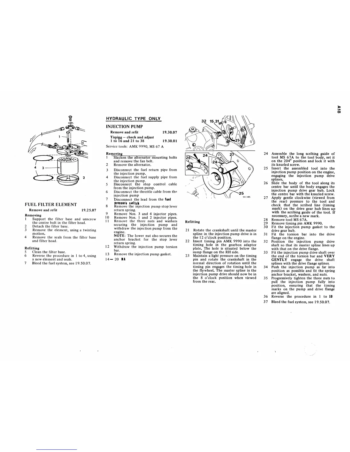
24
Assemble
the
long
scribing guide
of
tool
MS
67A
to
the
tool
body,
set
it
on
the
204
0
position
and
lock
it
with
its knurled screw.
25 Insert the assembled
tool
into
the
injection
pump
position
on
the
engine,
engaging
the
injection
pump
drive
splines.
26
Slide
the
body
of
the
tool
along its
centre
bar
until
the
body
engages
the
injection
pump
drive gear hub. Lock
the
centre
bar
with
the
knurled screw.
27
Apply gentle clockwise (viewed from
the
rear) pressure
to
the
tool
and
check
that
the
scribed line (timing
mark)
on
the
drive gear
hub
lines
up
with
the
scribing guide
of
the
tool.
If
necessary, scribe a new mark.
28
Remove
tool
MS
67A.
29
Remove timing pin
AMK
9990.
30
Fit
the
injection
pump
gasket
to
the
drive gear hub.
31
Fit
the
torsion bar in
to
the drive
flange
on
the
engine.
32
Position the injection
pump
drive
shaft
so
that
its master spline lines
up
with
that
on
the
drive flange.
33
Fit
the
injection
pump
drive shaft over
the
end
of
the torsion
bar
and VERY
GENTLY
engage
the
drive shaft
splines with
the
drive flange splines.
34
Push
the
injection
pump
as
far
into
position
as
possible
and
fit
the
spring
anchor
bracket, washers, and nuts.
35 Progressively tighten the three
nuts
to
pull
the
injection
pump
fully
into
position, ensuring
that
the
timing
marks
on
the
pump
and
drive flange
are aligned.
36
Reverse
the
procedure in I
to
10
37
Bleed
the
fuel system, see 19.50.07.
,..
....
00
 Loading...


