ALTERNATOR/REGULATOR
SERVICE
3.
Tum the starting switch
key
to the
ON
position, and the
voltmeter will indicate a value considerably lower than
the battery voltage. If the indication is near the battery ·
voltage, a defective generator is possible.
4. With the ammeter short-circuited, start the engine.
A
CAUTION:
lithe
ammeter
is
IIIJt
short·t:ir·
culled,
a
large
starting
t:llrrent
will
bum
out
the
ammeter
t:Dil.
5. Increase the engine
s~ed
to
between 2000 and 3000 rpm
and read the ammeter.
6.
If
the ammeter reading does not exceed 5A, read the
voltmeter at that state
(2000-3000 rpm).
The
voltmeter
reading is the regulated voltage.
7.
If
the ammeter reading exceeds SA, continue charging
the battery until the ammeter reading drops to
5A
or
below;
or
replace the battery with a fully-charged one;
or
connect a 1/40 (25W) resistor
in
series
to
the battery to
restrid charging current.
8.
The
IC
regulator is
of
the temperature compensation type
and, therefore, regulated voltage varies with temperature.
It
is necessary to measure the temperature
of
the rear
bracket (surrounding the regulator) and
to
use the
measurement for corredion
of
regulated voltage.
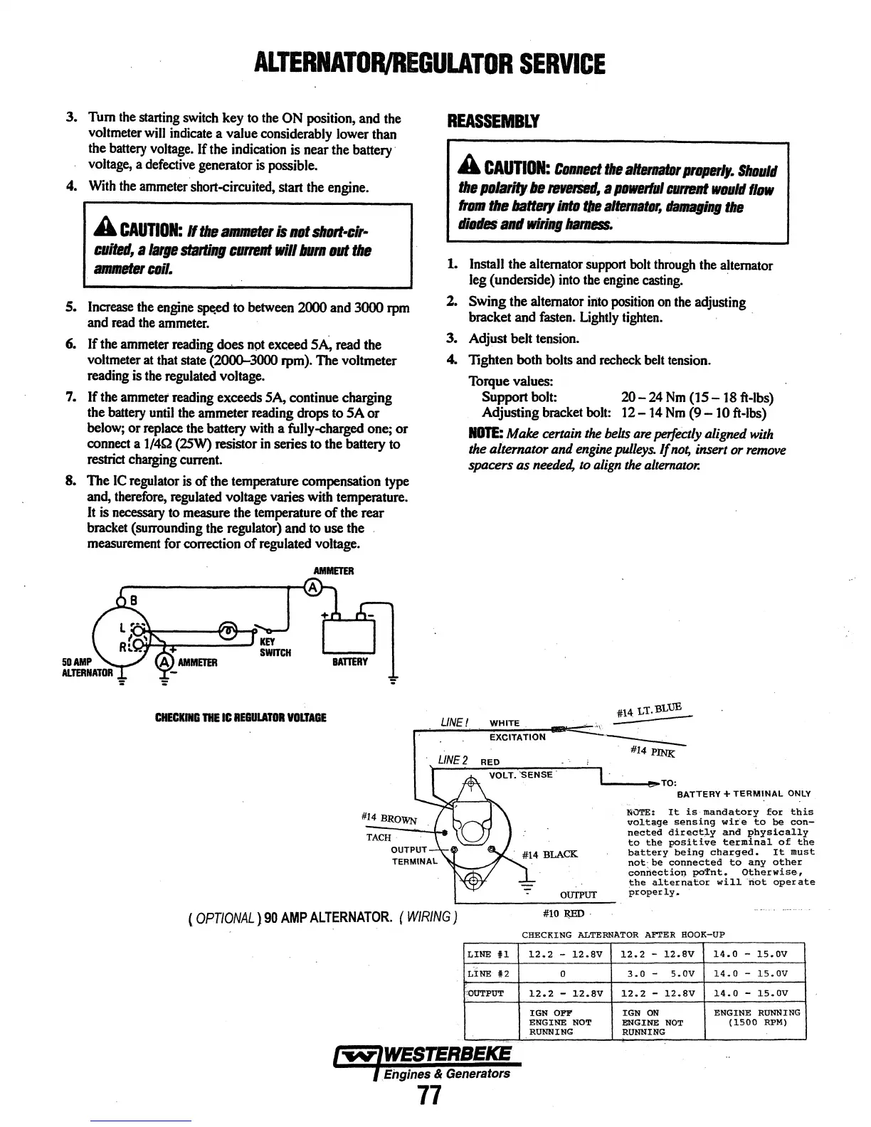
CHECKING
THE
IC
REGULATOR
VOLTAGE
REASSEMBLY
A
CAUTION:
Connect
the
altematDr
properly.
Should
the
polarity
be
reversed,
a
powerful
current
would
flow
from
the
battery
into
the
alternator,
damaging
the
diode$
and
wiring
harness.
1. InstaJI the alternator support bolt through the alternator
leg (underside) into the engine casting. ·
2.
Swing
the alternator into position on the adjusting
bracket and fasten. Lightly tighten.
3.
Adjust belt tension.
4.
lighten
both bolts and recheck belt tension.
Torque values:
Support bolt:
20-
24
Nm
(15-
18 ft-lbs)
Adjusting bracket
bolt:
12-14
Nm
(9-
10 ft-lbs)
NOTE:
Make certain
the
belts
are
perfectly
aligned
with
the alternator and
engine
pulleys.
If
not,
insert
or
remove
spacers as
needed,
to
align
the
alternator.
LINE!
WHITE
EXCITATION
·--:--
#14
PlNI{
'----!~TO:
BATTERY+
TERMINAL
ONLY
NOTE:
It
is
mandatory
for
this
voltage
sensing
wire
to
be
con-
nected
directly
and
physically
to
the
positive
terminal
of
the
battery
being
charged,
It
must
not·be
connected
to
any
other
connectioQ
pafnt.
Otherwise,
the
alternator
will
not
operate
properly.
(OPTIONAL)
90
AMP
ALTERNATOR.
(
WIRING)
#10
RED·
CHECKING
ALTERNATOR
AFTER HOOK-UP
LINE
fl
12.2
-
12.SV
12.2
-
12.8V
14.0
-
15.0V
LINE
i2
0
3.0
-
s.ov
14.0
-
15.0V
cOUTPUT
12.2
-
l2.8V
12.2
-
12.8V
14.0
-
15.0V
IGN OFF
IGN
ON
ENGINE
RUNNING
ENGINE
NOT
ENGINE
NOT
(1500
RPM)
RUNNING
RUNNING
Engines & Generators
77