TESDNG
STATOR
WINDINGS
VERY
LOW
VOLTAGE,
OR
NO
VOLTAGE
REFER
TO
THE
WIRING
SCHEMATICS
TROUBLESHOOTING
GUIDES.
AND
COMPONENT.
RESISTANCE
&
CHARTS
IN
THIS
MANUAL
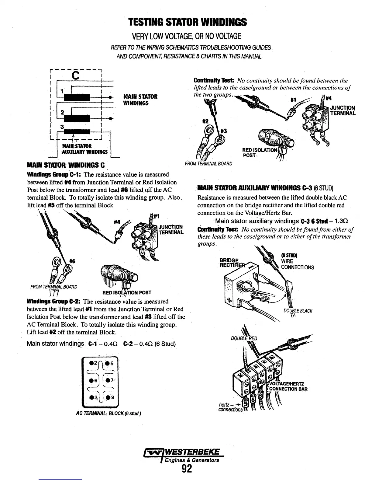
MAIN
STATOR
WINDINGS
MAll
STATOR
WIND.GS
C ..
FROM
TERMINAL
BOARD
Whidings
Group
G-1:
The resistance value
is
measured
between
lifted #4 from Junction Terminal or Red Isolation
Post
below
the transformer and lead
16
lifted off
:the
AC
terminal
Block.
To
totally isolate this winding group. Also ,
lift
lead
#5 off
the
~rminal
Bl~k
.\
t
FROM
TERM/~
BOARD
-
f~
.
R~l
~~P~T
rt . 1
,.,
W"mdings
Group
G-2:
The resistance value is measured
be~ween
the
lifted lead 11 from
the
Junction Terminal or
Red
Isolation
Post
below
the transformer and lead #3 lifted off the
AC
Terminal
Block.
To
totally isolate this winding group.
Lift
lead
#2 off
the
terminal Block.
Main
stator
winding_s.
c-1 """0.40
c-2-
0.40
(6
Stud)
AC
TERMINAL1
BLOCK
(6
Stud
J
.
·MAIR
STATOR
AUXII.IARY
WINDINGS
t:-3
(6
STUD)
Resistance is measured
between
the
lifted
double
black
AC
connection on the bridge rectifier
and
the
lifted
double
red
connection on the Voltage/Hertz
Bar.
_
'¥ain
stator auXiliary
windings
c-3 6
Stud-
1.30
c.tinuftY
Test:
No
continuity should
be
found
from either
of
these leads to the case/ground or
to
either
of
the
transformer
croups.
OLTAGEIHERTZ
!
\NNECOON
BAft
.
-
..
.
Engines & Generators
92