COMPOUND
TRANSFORMER
REFER
TO
THE
WIRING
SCHEMATICS
TROUBLf;SHOOTING
GUIDES
AND
COMPONENT,
RESISTANCE
&
CHARTS
IN
THIS
MANUAL
·1
~~
~
:
.2
~
I
==#=·I
·I::
3;
~~~~·H~P~
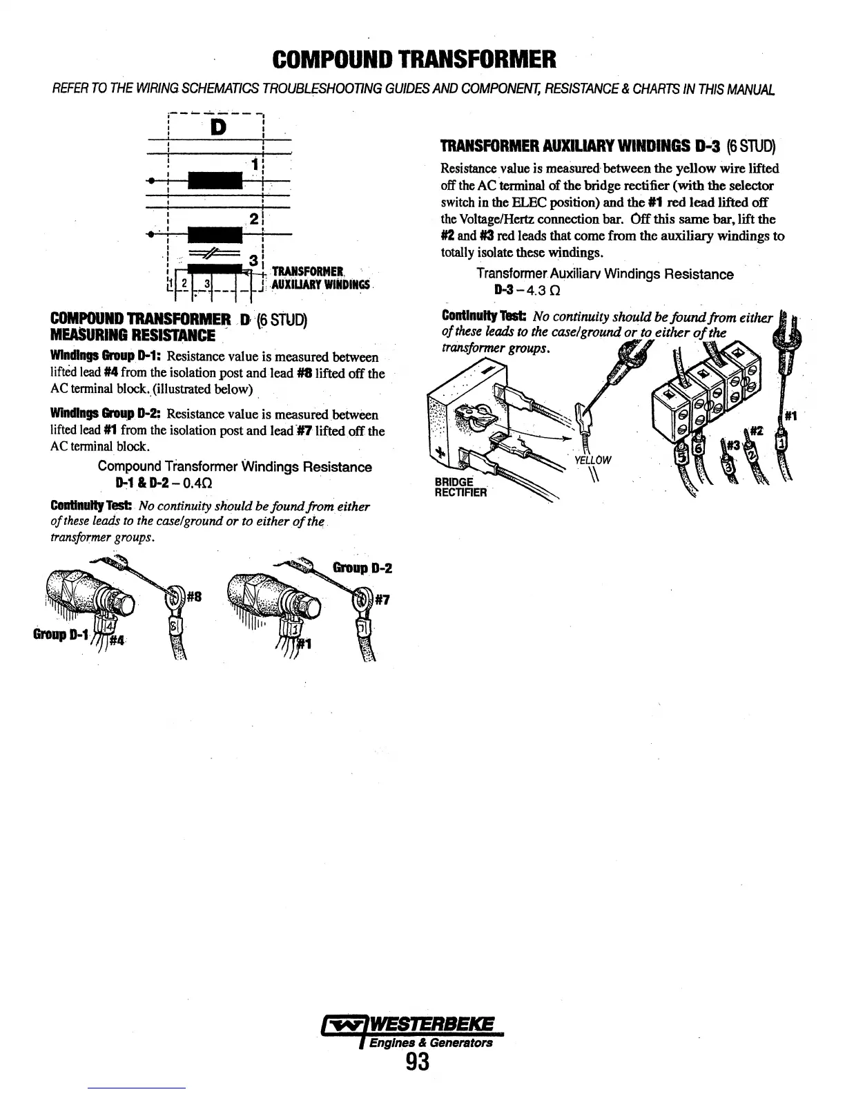
COMPOUND
TRANSFO-EI_l.
D
:{9
Si\JD)
MEASURIII
RESISTANCE
. ·
Windings
&roup
D-1:
Resistance value is measured between
lifted
lead
#4
from
the
isolation post and lead #&lifted off the
AC
tenninal
block
..
(illustrated below) .
Windings
Grolgt.
D-2:
Resistance value is measured between
lifted
lead
#1
from
the
isolation post and lead
~#?lifted
off the
AC
tenninal
block.
·
Compound
Transformer
Windings Resistance
~1
&D-2-0.40
.
C8llllnally
Test
.
No
continuity should be found from either
of
these
lea.dS
to the case/ground or
to
either
of
the,
. .
tran.sfor:mer
groups.
TRANSFORMER
AUXILIARY
WINDINGS
g.;3
(6
STUD)
Resistance
value
is
measured·
between the yellow wire lifted
off
the
AC
·tenninal of the bridge rectifier (with the selector
switch
in
the
ELBC
position) and the
#1
red
lead lifted off
the
Voltage/Hertz
connection bar. Off this same bar, lift the
#2
and
#3
red leads that come from the auxiliary windings to
totally
isolate these windings.
TransformerAuxiliarv
Windings
Resistance
D-3-4.3
n
ConUnaiiJ
Test
No
continuity should be
found
from
eitlle.r
of
these
leads
to
the
caselgrowui or
to
either
of
the
trrinsjormer
groups.
·
~·
Sl
/''W¥'1WESIERBEICB
l Eng/IJIIS & Generators
93