VOLTAGEADJUSniENTS
NO-LOAD
VOLTAGE
ADJUSTMENT
Voltage
adjustment
is
made
with the generator regulation
being
governed
by
the compound transfonner. ·
l.
The
selector switch
[if
applicable] must be in the comp
position
2.
to
confirm
no-load voltage, start the generator and apply a
momentary
(moderate)
load to excite the transformer. The
voltage
produced by the generator after
the
momentary
load
is
removed
is
no-load voltage. Note the voltage
output
from the generators
120
volt leg(s) (230 volt 50
hertz).
The
no-load voltage should be between 121-124
volts
at 615-62 hertz (232-236 volts at 515-52 hertz).
3.
To
raise
or lower the voltage, shims
of
varying thickness
(non-conductive
material)
are
placed
or
removed from
under
the
steel
laminated bar on top
of
the compound
transformer.
The material used for shimming should not
soften
at temperatures in the
176°
(80°
C)
range. A small
reduction
in no-load voltage
(1
to
3 volts) am sometimes
be
accomplished
by
gently
tapping the top
of
ihe laminated
steel
bar
to
reduce the
gap
]Jetweetf1he existing shims and
the transfonner core. Varying the shim thickness by
,001
inch (0.025mm) will change the No Load voltage
byA-6.Y.Olts.
Fli'LL·LOAD
VOLTAGE
ADJUSTMENT
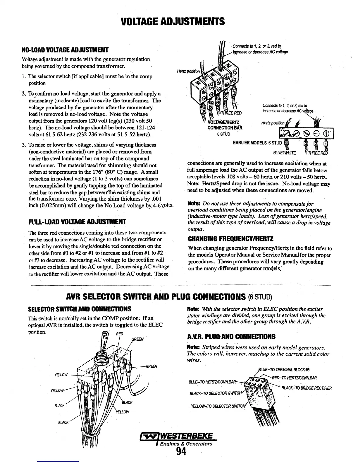
The
three
red
connections coming into these two components
·
can
be
used
to
increase
AC
voltage to the bridge rectifier or
lower
it
by
1noVinithe single/double red connection on the
other
side
from
#3
to
12 or
#1
to increase and from #l.to 12 ·
or
#3
to
decrease.
Increasing AC voltage to the rectifier
will
increase
excitation
and
theAC output. Decreasing AC voltage
..
to
the
reCtifier
will
lower excitation. and the AC
Output.
Tliese
THREE
RED
'
VOLTAGEIHERTZ
CONNEcTION
BAR.
6STUD
Connects
to
1,
2,
or
3,
ted
to
increase
or
decrease
AC
voilage
.
EARUER
MODELS
6
STUD
6
.connections
are generaliy used to increase excitation when at
full
amperage load the
At
output
of
the generator fails below
acceptable levels
108
volts-
60 hertz or 210
volts-
50 hertz.
Note:
Hertz!Speed
drop
is not the issue, No-load voltage may
·
need
to be adjusted when these connections are moved.
ltGta:
Do
not
use
these adjustments
to
compensate for
overload
cqndltions being placed
o.n
the
generator/engine
(inductive-motor
type
loads).
Loss
of
generator
hertz/speed,
the
result
of
this
type
of
overload, will cause a
drop
in
voltage
output.
CHANGING
FREQUEICYIHERTZ
When changing generator Frequency/Herq in the
field
refer to
the models Operator Manual or Service Manual for the proper
procedures.
Thes~
procedures will vary greatly depeiiding
on
the many different generator
ni'odels.-
AVR
SELECTOR
SWITCH
AND
PLUG
CONNECTIONS
·(s
STUD)
SELECTOR
SWITCH
AND
COINECTIOIIS
This
'SWitch
is
norhlally set
in
the COMP position;
If
an
optio_l;llll
AVR
is installed, the switch is toggled to the ELEC
position.
·
~
·~
"i
.....
...
J
~
YElLOW
Nate:
Wfth
the
selector switch
in
ELEC
position
the
exciter
stator
windings
are
divided,
one
group
is excited
through
the
bridge
rectifier·
and
the
other
group
through
the
A.V.R.
A.V.R.
PI..UG·AitD
COIIIECDONS
Nate:
Striped wires were used on early motkl generators.
The colors will,
however,
matchup to the cu"ent solid color
wires.