BT
GENERATOR
VOLTAGE
REGULATOR
ADJUSTMENTS
(3
PHASE)
Description
The
voltage regulator is an advanced
design
which
ensures
optimum
AC
generator performance. It is equipped with
~omplete
protection circuitry to guard against operating
conditions
that
could
be
detrimental
to
the
AC
generator.
This
potentiometer is used to adjust output voltage. At proper
engine
operating speed the output voltage should
be
held
at
±1%
from
a no-load condition
to
a
full
rated generator output
and
from
power factor 1.0 - 0.8 with engine drive speed
variations
up
to -6%. Prior to starting
the
engine, turn
the
VOLT
and
STAB
trimmers (using a mini phillips
screw-
driver)
fully in a counter clockwise (Minimum) direction
until
you
feel them
bit
their stops.
Thrn
the
AMP
and
HERTZ
trimmers completely clockwise (Maximum)
in
the
same
manner.
With the
ge~erator
running at no-load, at
normal
speed, and with VOLT adjust at minimum, it
is
possible
that output voltage will oscillate. Slowly rotate
the
VOLT
adjust clockwise.
The
voltage output will increase
and
stabilize.
Increase tlte voltage to the desired value. In
this
situation,
only
the green LED will
stay
lit.
Stability
This
potentiometer
_permits
vari~on
of
the
regulator's
response
to
generator load changes
so
as
to
limit
overcom-
pensation
and
obtain a minimum
recovery
time
to
the
normal
voltage
output.
In
order
to
adjust the ragulator stability the generator
must
be
running
at no-load and the
o~tput
must
be
monitored.
Turn
the
sru adjust slowly clockwise until the voltage
starts
to
fluctuate.
At
this point rotate the
.STAB
adjust
coun-
te~lockwise
until the voltage is stable within 1 or 2
tenths
of
a
volt.
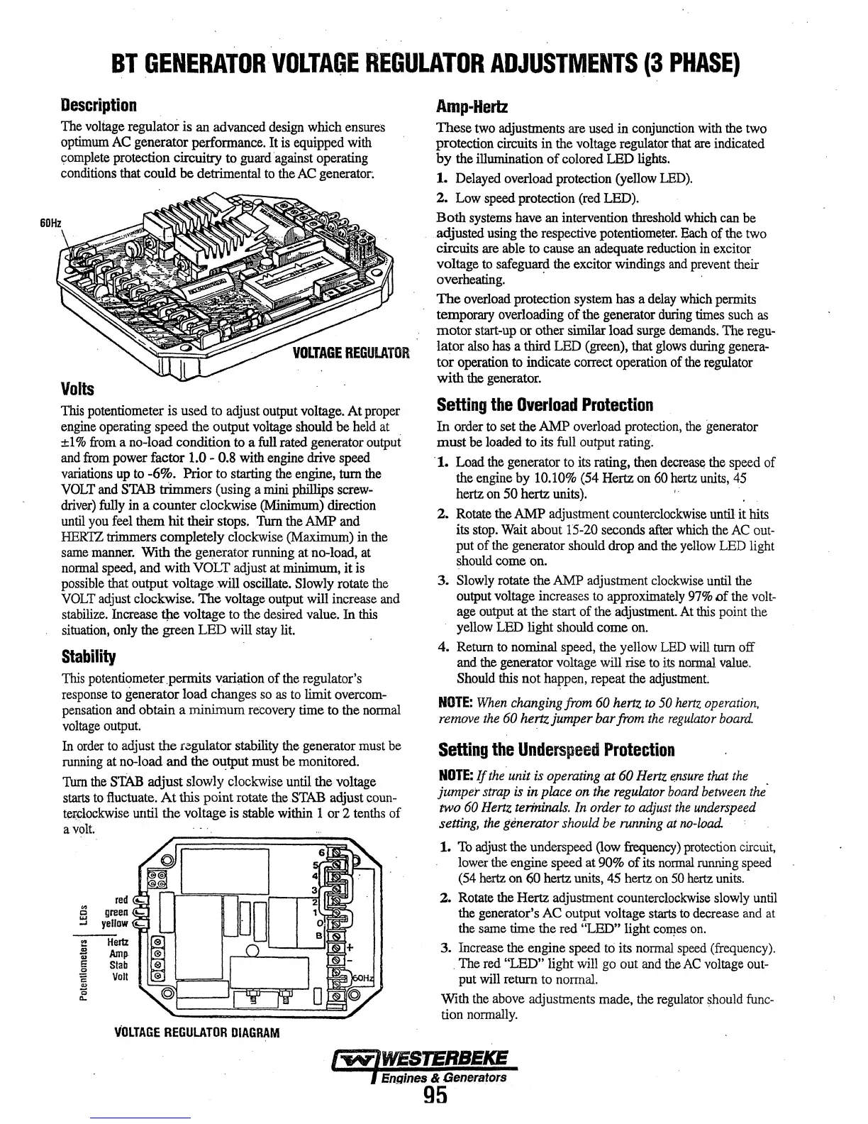
VOLTAGE
REGULATOR
DIAGRAM
Amp-Hertz
These
two
adjustments are used in
conjunction
with
the two
protection circuits in the voltage regulator
that
are
indicated
by
the illumination
of
colored
LED
lights.
1. Delayed overload protection (yellow LED).
2.
Low
speed protection (red LED).
Both
systems
have
an
intervention
threshold
which
can be
adjusted using the respective potentiometer.
Each
of
the
two
circuits
are
able to cause
an
adequate
reduction
in
excitor
voltage
to
safeguard the excitor windings
and
prevent
their
overheating.
· ·
The
overload protection system has a
delay
which
pemrlts
temporary overloading
of
the generator
during
times
such
as
motor start-up or other similar load
surge
demands.
The
regu-
lator
also
has
a third
LED
(green), that
glows
during
genera-
tor operation
to
indicate correct operation of
the
regulator
with
the generator.
Setting
the
Overload
Protection
In
order
to
set the
AMP
overload
protection,
the
generator
must
be
loaded to its full output rating.
·1. Load the generator
to
its
rating, then
decrease
the
speed of
the engine by
10.10% (54 Hertz
on
60
hertz
units,
45
hertz
on
50
hertz units). ·
2. Rotate the AMP adjustment counterclockwise until it hits
its
stop.
Wait about 15-20 seconds
after
which
the
AC
out-
put of
the
generator should drop and
the
yellow
LED
light
should
come
on.
3.
Slowly
rotate the
AMP
adjustment
clockwise
until the
output voltage increases
to
approximately
97%
Df
the
volt-
age
output at the start of the adjustment.
At
this
point
the
yellow
LED
light should come
on.
4.
Return
to
nominal speed, the yellow
LED
will
turn off
and
the
generator voltage will rise to
its
normal
value.
Should this not happen, repeat
the
adjustment.
NOTE:
When
changing
from
60
hertz
to
50
hertz
operation,
remove
the
60
hertz jumper bar
from
the
regulator
board.
Setting
the
Underspeed
Protection
NOTE:
If
the.
unit is
operating
at
60
Hertz
e.nsure
that
the
jumper
strap
is
in
place
on
the
regulator
board
between
the·
two
60
Hertz
terininals.
In
order
to
adjust
the
underspeed
setting,
the
generator should
be
running
at
no-load.
1.
To
adjust
the underspeed
(low
frequency)
protection
circuit,
lower
the
engine speed at
90%
of
its
normal
running
speed
(54
hertz
on
60 hertz
units,
45
hertz
on
50
hertz
units.
2. Rotate the Hertz adjustment counterclockwise
slowly
until
the
generator's
AC
output voltage
starts
to
decrease
and
at
the
same
time the red "LED" light
co~es
on.
3. Increase the engine speed
to
its
normal
speed
(frequency)
.
. The red "LED" light
will
go
out
and
the
AC
voltage
out-
put
will
return
to
normal.
With the
above
adjustments made, the
regulator
should
func-
tion
normally.
I...,IWE&TERBEKE
f
Engines
&
Generators
95
 Loading...

