AUTOMOTIVE PRODUCTS, INC.
INSTRUCTIONS-INSTRUCCIONES-CONSIGNES
1
2
3
4
11
75-0757 REVISION D 6/30/08
WO:
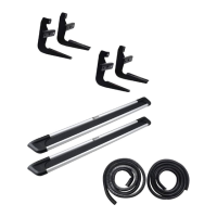
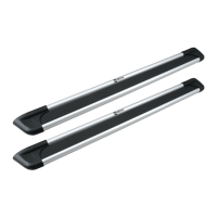
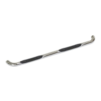
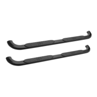
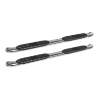
1 2 STEP BOARD (PURCHASED SEPARATELY)
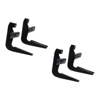
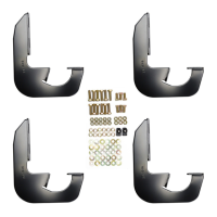
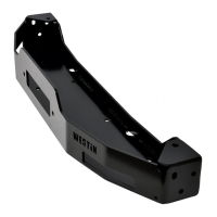
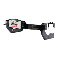
2 2 FRONT BRACKET
3 2 CENTER BRACKET
4 2 REAR BRACKET
5 12 5/16-18 X 1.00” HEX HEAD BOLT
6 30 5/16” USS FL AT WASHER
7 12 5/16” LOCK WASHER
8 6 5/16-18 HEX NUT
9 12 5/16-18 X .75” SQUARE HEAD BOLT
10 12 5/16-18 LOCK NUT
11 6 EXTRUDED U-NUT
QTY
CONTENTS - CONTENIDO - CONTENU
TOOLS-HERRAMIENTA
-OUTILS
1/2” SOCKET
1/2” WRENCH
RATCHET
RATCHET EXTENSION
TORQUE WRENCH
ITEM
1 2 ESTRIBOS (SE COMPRAN POR SEPARADO)
2 2 SOPORTES DELANTERAS
3 2 SOPORTES CENTRALES
4 2 SOPORTES TRASERAS
5 12 PERNOS CON CABEZA HEXAGONAL DE 5/16-18 X 1,00”
6 30 ARANDELAS PLANAS DE USS 5/16”
7 12 ARANDELAS DE PRESIÓN DE 5/16”
8 6 TUERCAS HEXAGONALES DE 5/16-18
9 12 PERNOS CON CABEZA CUADRADA DE 5/16”
10 12 TUERCA PRESIÓN DE 5/16-18
11 6 TUERCA A PRESIÓN EN “U”
1 2 MARCHEPIED (VENDU SÉPARÉMENT)
2 4 SUPPORTS AVANT
3 2 SUPPORTS CENTRAL
4 2 SUPPORTS ARRIERE
5 12 BOULONS A TETE HEXAGONALE 5/16-18 X 1,00 PO
6 30 RONDELLES PLATES USS 5/16 PO
7 12 RONDELLES A FREIN 5/16 PO
8 6 ÉCROUS HEXAGONAUX 5/16-18
9 BOULON A TETE CARREE 5/16 PO
10 12 ECROU A FREIN 5/16-18
11 6 ECROU EN U EXTRUDE
12
DADO DE 1/2”
LLAVE DE TUERCAS DE 1/2”
MANERAL
MANERAL EXTENSION
LLAVE DE TORQUE
DOUILLE 1/2 PO
CLEF 1/2 PO
CLIQUET
CLIQUET RALLONGE
CLÉ DE COUPLE
STEP 1. Remove contents from box and check for damage. Verify all parts are present. Read and understand instructions before beginning.
NOTE: If installing Westin step boards on vehicles equipped with factory step boards, the existing factory hardware can be used. The
mount brackets will be placed over the mounting stud protruding from the rocker panel, and the factory nuts can be reused. It is
strongly recommended to install the Sure Grip Gap Strip for these vehicle applications.
STEP 2. Locate the pair of holes on the bottom of the rocker panel and the square hole next to the round hole on the bottom of the floor
pan. SEE FIGURE 1.
STEP 3. Insert extruded “u” nut through square hole in vehicle floor plan so it is positioned over the round hole. SEE FIGURE 1.
STEP 4. Install front, center, and rear brackets to the extruded “u” nuts inserted into the vehicle floor pan with 5/16” fasteners as shown. SEE
FIGURE 1.
STEP 5. Install front, center, and rear brackets to vehicle rocker panel with 5/16” fasteners as shown. SEE FIGURE 1 for hole locations.
STEP 6. Insert square head bolts as shown (3 per slot, 6 per Step board/Running board). See Figures 3 and 4. NOTE: For lighted boards, run
wiring harness prior to attaching board to brackets (refer to Step 4). SEE FIGURES 3 AND 4. Run longer wire harness on passenger
side.
STEP 7. For Sure-Grip Running Boards, slide closure strip as shown. Set lights (if purchased) in appropriate location. Attach to Sure-Grip Running
Board as shown. SEE FIGURE 2. Drill hole through plastic strip and run wires as shown. SEE FIGURE 5.
STEP 8. Attach Step board / Running board to brackets as shown. Make sure step board and brackets are properly aligned and tighten
fasteners. Recommended torque values are 10 FT.LBS. for 5/16” square head fasteners and 16 FT.LBS. for 5/16” fasteners. SEE
FIGURE 6. NOTE: For lighted version of Step board, remove plastic cover from each end of under side of Step board. Proceed to
Steps 9 and 10.
WARNING: INSTALLING LIGHT HARNESS REQUIRES SPLICING INTO VEHICLES ELECTRICAL SYSTEM. WESTIN RECOMMENDS USING A PROFESSIONAL
FOR THIS INSTALLATION. NOTE: AVOID AREAS OF EXCESSIVE HEAT, VIBRATION, PINCH OR ROTATION WHEN SECURING HARNESS TO
APPLICATION: 2006-08 FORD EXPLORER; MERCURY MOUNTAINEER
APLICACIÓN: FORD EXPLORER/ MERCURY MOUNTAINEER, MOD.2006-08
APPLICATION: 2006-08 FORD EXPLORER/ MERCURY MOUNTAINEER
MOUNT KIT
EQUIPO DE MONTAJE
JEU DE MONTAGE
27-1675
MOLDED
STEP
BOARDS
27-0010
27-0015
SURE-GRIP
OPTIONAL LIGHT
KIT
27-6000
SURE-GRIP
BOARDS
27-6130
27-6135
27-6530