EasyManua.ls Logo

Westin 27-1845 User Manual

Westin 27-1845
3 pages
To Next Page IconTo Next Page
Page #1 background imageLoading...
Page #1 background image
AUTOMOTIVE PRODUCTS, INC.
5
6
(1) (2)
(4) (5)
1,2 2 ESTRIBOS, ACOMPAÑANTE Y CONDUCTOR
3,4 2 SOPORTES DELANTERAS, CONDUCTOR (3), PASAJERO (4)
5,6 2 SOPORTES , PASAJERO Y CONDUCTOR
7 8 SUELDE NUEZ 3/8-16
8 8 PERNOS CON CABEZA HEXAGONAL DE 3/8-16 X 1,25”
9 8 ARANDELAS PLANAS DE 3/8”
10 8 ARANDELAS DE PRESIÓN DE 3/8”
11 8 TUERCAS HEXAGONALES DE 3/8-16
ARANDELAS PLANAS DE 5/16”
ARANDELA DE PLÁSTICO
(SE COMPRA
SEPARADO)
12 8 PERNOS CON CABEZA CUADRADA DE 5/16”
13 8
14 8 TUERCA PRESIÓN DE 5/16-18
TRASERAS
15 8
(1) CONDUCTEUR (2)
(3) PASSAGER (4)
(5) CONDUCTEUR (6)
7 8 SOUDER LA NAUX 3/8-16
BOULON A TETE HEXAGONALE DE PO
9 RONDELLE PLATE DE 3/8 PO
10 8 RONDELLE A FREIM DE 3/8 PO
11 8 ÉCROUS HEXAGONAUX 3/8-16
12 8
RONDELLE PLATE DE 5/16 PO
1,2 2 MARCHE-PIEDS, PASSAGER ET
3,4 2 SUPPORTS AVANT, CONDUCTEUR ET
5,6 2 , PASSAGER ET
8 8 3/8-16 X 1,25
8
(ACHETE
SEPAREMENT)
BOULON A TETE CARREE 5/16 PO
13 8
14 8 ECROU A FREIN 5/16-18
SUPPORTS ARRIERE
15 8 RONDELLE DE PLASTIQUE
LLAVE DE TUERCAS DE 9/16”
LLAVE DE TUERCAS 1/2”
DESTORNILLADOR PHILLIPS
MANERAL
LLAVE DE TORQUE
DOUILLE 9/16 PO
DOUILLE 1/2 PO
TOURNEVIS A POINTE CRUCIFORME
CLIQUET
CLEF DE COUPLE
QTY
CONTENTS - CONTENIDO - CONTENU TOOLS - HERRAMIENTA
- OUTILS
ITEM
1,2 2 STEP BOARD, PASSENGER (1) AND DRIVER (2) (PURCHASED
SEPARATELY)
3,4 2 FRONT BRACKET, DRIVER (3) AND PASSENGER (4)
5,6 2 REAR BRACKET, PASSENGER (5) AND DRIVER (6)
7 8 3/8-16 BRIDGE WELD NUT
8 8 3/8-16 X 1.25” HEX HEAD BOLT
9 8 3/8” FLAT WASHER
10 8 3/8” LOCK WASHER
11 8 3/8-16 HEX NUT
12
15 8 PLASTIC WASHER
8 5/16-18 X .75” SQUARE HEAD BOLT
13 8 5/16” FLAT WASHER
14 8 5/16-18 LOCK NUT
9/16” SOCKET
1/2” SOCKET
PHILLIPS SCREWDRIVER
RATCHET
TORQUE WRENCH
STEP 1. Remove the contents from box and check for damage. Verify all parts are present. Read instructions completely
before beginning. NOTE: Westin does not recommend the closure strip for this application.
STEP 2. Remove rubber plugs from vehicle body. NOTE: rubber plugs may be hidden by the factory undercoating.
STEP 3. Thread 3/8-16 x 1.25” hex head bolts through bridge weld nuts, insert into holes, and use plastic washers to hold in
place. SEE FIGURES 1 AND 2.
STEP 4. Attach driver side brackets to the previously assembled 3/8” bolt plate using four 3/8” flat washers, 3/8” lock washers,
and 3/8-16 hex nuts as shown. SEE FIGURES 1 AND 2.
MOUNT KIT
EQUIPO DE MONTAJE
JEU DE MONTAGE
27-1845
STEP BOARD
ESTRIBOS
MARCHEPIED
27-6110
27-6115
27-6510
1
/
2
3
4
W11-0994 75-0851 REVISION C 5/29/13
INSTRUCTIONS-INSTRUCCIONES-CONSIGNES
APPLICATION: 2007-12 HYUNDAI SANTA FE
APLICACIÓN: , MOD. 2007-12HYUNDAI SANTA FE
APPLICATION: HYUNDAI SANTA FE 2007-12
Question and Answer IconNeed help?

Do you have a question about the Westin 27-1845 and is the answer not in the manual?

Westin 27-1845 Specifications

General IconGeneral
BrandWestin
Model27-1845
CategoryAutomobile Accessories
LanguageEnglish

Summary

Parts and Tools Identification

English Parts List

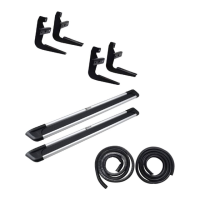
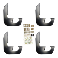
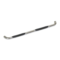
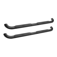
Lists item numbers, quantities, contents, and required tools for the Westin Step Board installation.

Spanish Parts List

Detalla los números de artículo, cantidades, contenido y herramientas necesarias para la instalación del estribo Westin.

French Parts List

Liste les numéros d'articles, les quantités, le contenu et les outils requis pour l'installation de la marchepied Westin.

Installation Procedure

Step 1: Inventory and Preparation

Remove contents from the box, check for damage, and verify all parts are present before starting.

Step 2: Vehicle Body Preparation

Remove rubber plugs from the vehicle body, noting they might be hidden by factory undercoating.

Step 3: Initial Bolt Assembly

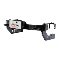
Thread 3/8-16 x 1.25" hex head bolts through bridge weld nuts and insert into holes with plastic washers.

Step 4: Driver Side Bracket Attachment

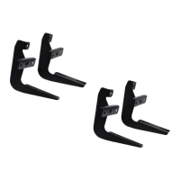
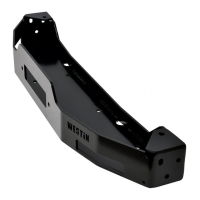
Attach driver side brackets to the 3/8" bolt plate using specified washers and hex nuts.

Step 5: Square Head Bolt Insertion

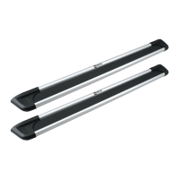
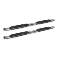
Insert square head bolts into the step board slots as illustrated, with 2 per slot and 4 per board.

Step 6: Step Board Mounting and Securing

Mount the step board to the brackets, remove rear end cap screws, and secure the board to clamp the cap.

Step 7: Passenger Side Installation

Repeat the entire installation procedure for the passenger side of the vehicle.

Finish Protection Recommendations

Care for High-Quality Finish

Protect the product's finish regularly with a non-abrasive automotive wax to prevent scratches and corrosion.

Related product manuals