2 Wireless Device (WD)
Before reading this chapter it is recommended to read this sequence of specific IOMs: WH,
WG/R, WMS. This will prepare you to easily understand the terminology, functions and
operations described hereafter.
2.1.1 Wireless Device Overview
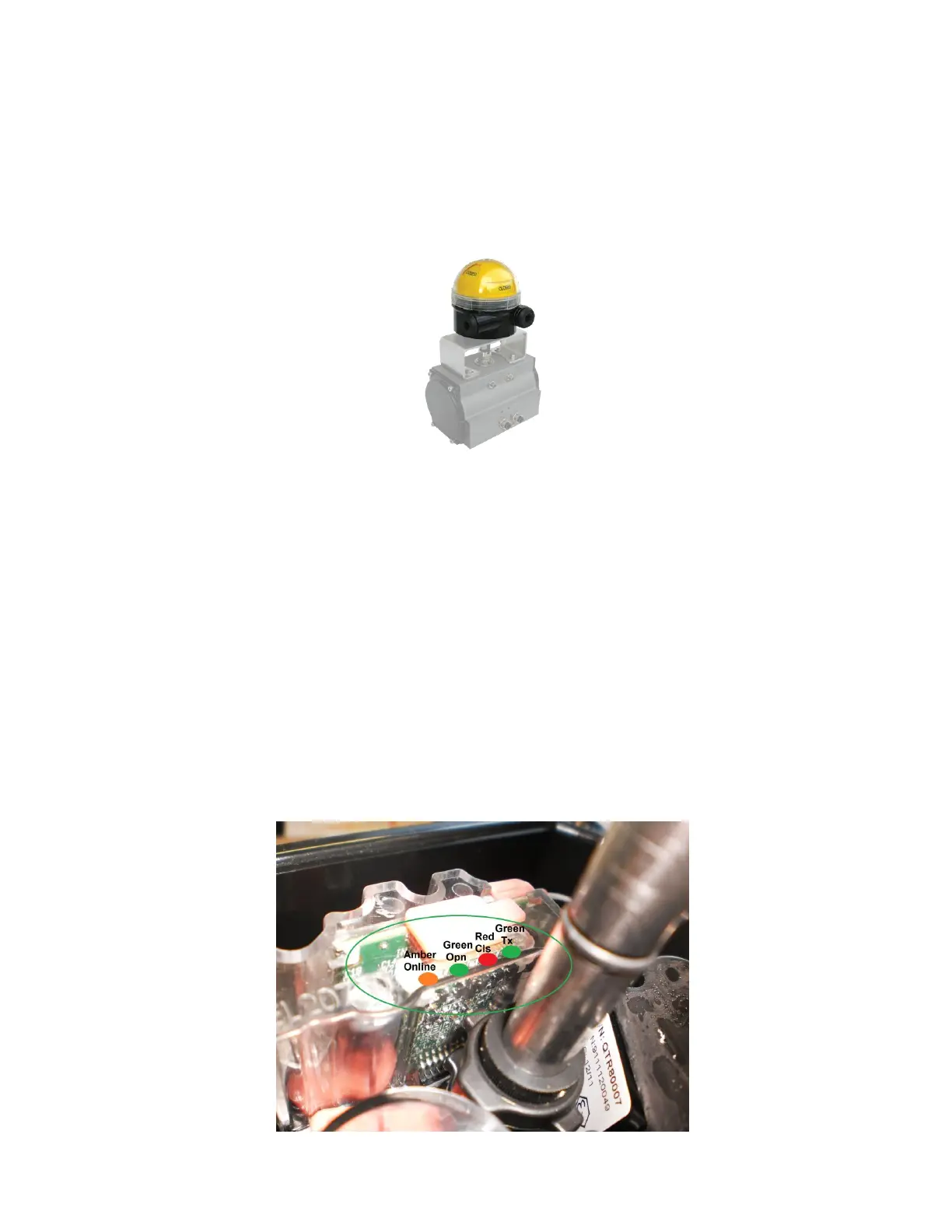
Figure 2: Wireless Device Internal Antenna Mounted on Actuator
The Westlock Wireless Device (WD) is the sensing component of the Westlock Wireless Valve
Monitoring System. It is installed on top of a valve or actuator and consists of a stem attached
mechanically to the valve or actuator axle. The WD includes sensors that measure the angle
which corresponds to the opening status of the valve (in degrees and opening percentage). The
valve status is transmitted by an internal bi-directional transceiver that is based on the standard
ZigBee Pro protocol. A dedicated Low Frequency (LF) receiver, in the WD, supports advanced
maintenance, calibration, and provisioning procedures by the Wireless Handheld (WH).
The WD provides real-time information about a valve’s status directly into the control system
thereby reducing failure and risk while increasing safety and yield.
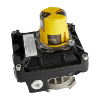
2.1.2 Wireless Device LEDS and Indicators
The WD has 4 internal LEDs for diagnostic. The LEDs are visible by removing the cover or
beacon or through the transparent cover, as shown in the following picture: