WESTLOCK CONTROLS CORPORATION
280 MIDLAND AVENUE, SADDLE BROOK, NJ 07663 TEL: 201-794-7650 FAX: 201-794-0913
www.westlockcontrols.com
1/24/12 TECH-455/D.W.O. 19909 Page 14 of 24
Each message is sent by the WD with a real time stamp.
125kHz (3 channels): Short range receiver continuously open,
even when WD is turned OFF: WD on/off, calibration,
identification, commissioning, test, etc.
WD internal temperature, battery voltage and unit's house-keeping
parameters.
A battery pack containing 4 Lithium ½ AA batteries. Field
replaceable where allowed by local regulations.
10 years under nominal conditions: four valve position changes
per hour and 20 millisecond sampling rate.
Valve Transition
Measurement
(optional)
After 1.50 degree move of valve, WD collects up to 64 readings of
valve position every 5 ms up to 9.8 sec (user selectable in discrete
steps) and all readings transmitted as a packet.
Both ZigBee Pro stack and MCU application can be upgraded
through the ZigBee link (Download Over Radio).
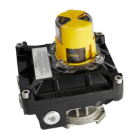
Internal canister made of clear Polycarbonate
2.1.4 WD Installation
The Westlock Wireless Device can be mounted on operating installed valves using an
appropriate bracket. Each valve type requires a unique mechanical design for the specific
bracket and Westlock has a large installed base and extensive experience manufacturing and
customizing such brackets. During site survey, Westlock determines the type of brackets
required for the installed valves on the process line.
Most brackets consist of two parts. One part connects the fixed part of the WD to the fixed part
of the valve, and the other connects the rotating part of the WD to the rotating part of the valve
(stem/shaft). Actuators with a NAMUR interface usually do not require the rotating part.
Specific installation instructions are provide in accordance with the provided WD brackets.