WESTLOCK CONTROLS CORPORATION
280 MIDLAND AVENUE, SADDLE BROOK, NJ 07663 TEL: 201-794-7650 FAX: 201-794-0913
www.westlockcontrols.com
1/24/12 TECH-455/D.W.O. 19909 Page 15 of 24
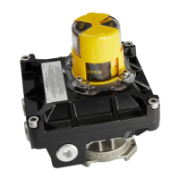
The WD has an effective valve position (angle) measurement range of about 110º. On the stem
of the WD, an axle spline indicates the position of the stem (valve). On the bottom of each WD
there are two etched marks indicting a range of 90º. This is the effective motion zone of the
WD's stem to measure the position of the quarter turn.
To avoid erroneous behavior, when installing the WD on a quarter turn valve or on an actuator
verify that the axle spline is always positioned between the two etched lines (the motion zone).
All WDs are factory calibrated such that the motion zone of the position measurement range is
centered. Do not remove the lower PCB from its casing, or factory calibration may be lost.
1. When installing the WD on a quarter turn valve or actuator, verify that the axle spline is
always positioned in the range between the two etched marks indicating the motion zone.
2. Perform the calibration procedures in order to ensure that the relative positions of the WD
and the valve are correct.
3. After mounting the WD on a valve or an actuator, calibrate the WD to set the open and
closed boundaries of the valve/actuator. Calibration is performed by the WH
communicating with the WD (refer to specific WH IOM). This process must be performed
locally using the WH via LF. This ensures the accuracy of the configuration.
If installation is performed on an active line, partial calibration can also be implemented. When
either the OPEN or CLOSED angle is set, the WD will automatically suggest the corresponding
other angle as 90 degrees away. To achieve partial calibration, reset previous calibration angles
prior to setting the current angle (RESET CAL function by WH).
The WD can also report a custom valve angle which has been preset in the process line to
facilitate a position report which is defined as CUSTOM. This third state provides the user
with the ability to return to a predefined setting for a particular valve. For example, the user sets
the valve to a capacity setting which will be reported upon by the WD to the WH and/or WMS
when the WD is within the tolerance values of the Custom state. This angle is always measured
from the 0 angle, regardless of valve angle notation (open or closed). The CUSTOM angle can
be set either on the WH (CAL > Set Custom by WH) or using the WMS.